
Compensation valve applied to hydrostatic braking system and hydrostatic braking system

A braking system and compensating valve technology, applied in the direction of hydraulic brake transmission, brake transmission, brakes, etc., can solve the problems of incomplete release of brake, inability to release, brake hysteresis, etc., and achieve rapid and thorough brake release , The effect of sensitive braking response

Active Publication Date: 2020-04-28
CHENGDU UNIVERSITY OF TECHNOLOGY
View PDF5 Cites 0 Cited by
  • Summary
  • Abstract
  • Description
  • Claims
  • Application Information

AI Technical Summary

Problems solved by technology

If a static pressure braking system is used, the liquid transmission medium in the pipeline can weigh hundreds of kilograms. Due to the potential energy pressure of the medium caused by the height difference and the flow resistance of the pipeline, the braking hysteresis will be caused, and the braking will not be released completely or even cannot be released.

Method used


Image

  • Compensation valve applied to hydrostatic braking system and hydrostatic braking system
  • Compensation valve applied to hydrostatic braking system and hydrostatic braking system

Examples


Embodiment 1

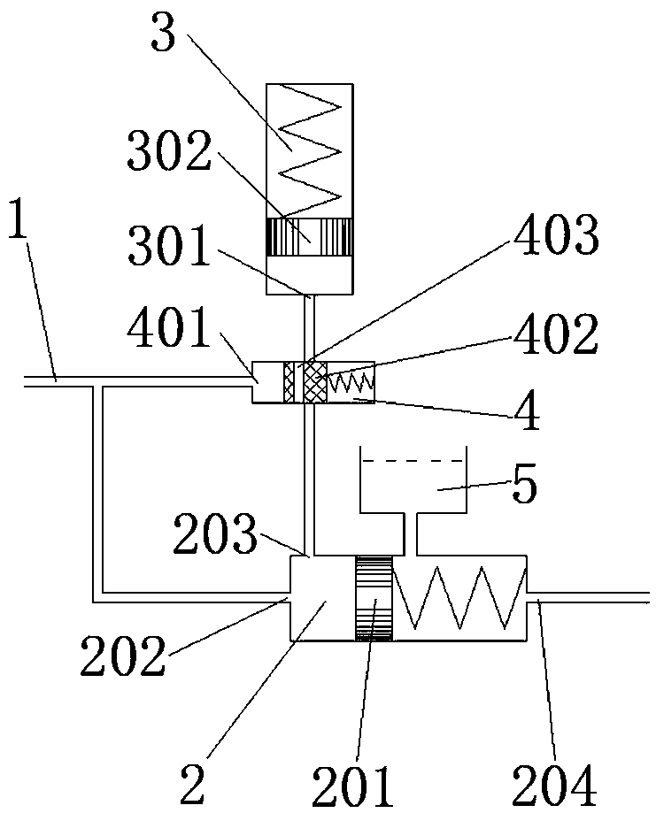
[0026] like figure 1 As shown, the purpose of the present invention is to propose a compensation valve, including: an input pipeline 1 for inputting liquid medium; an isolation chamber 2, in which an isolation piston 201 is provided, and the isolation piston 201 divides the cavity into left and right cavity and a right cavity, the left cavity is provided with a first liquid inlet 202 and a liquid replenishment port 203, and the first liquid inlet 202 is connected to the input pipeline 1; the right cavity is provided with a liquid outlet 204 for Output liquid medium, the isolation piston 201 is connected to the cavity near the liquid outlet 204 through a spring; the energy storage chamber 3 is used to store high-pressure liquid medium, and is provided with a pressure relief port 301, and the pressure relief port 301 is connected to the liquid replenishment port 203 is connected to form a compensation pipeline; the normally closed valve 4 is set on the compensation pipeline and ...

Embodiment 2

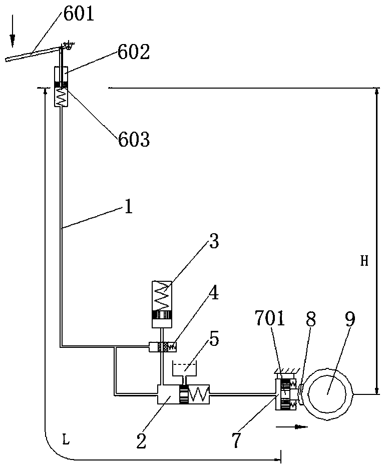
[0031] The present invention also proposes a static pressure braking system, which includes the above-mentioned compensating valve, the control end, and the brake chamber 7, the control end is connected with the input pipeline 1, and is used to push the liquid medium in the pipeline; the system The moving chamber 7 is connected to the liquid outlet 204, and a brake piston 701 is arranged inside through a spring, and the liquid medium enters the brake chamber 7 to push the brake piston 701 for braking.

[0032] In this embodiment, the operating end includes an operating rod 601 and an operating chamber 602, the operating rod 601 is connected to an operating piston 603 in the operating chamber 602, and the operating piston 603 is connected to the operating chamber 602 through a spring. The brake piston 701 is connected with a brake pad 8, and the brake pad 8 cooperates with a brake hub 9. When the brake piston 701 brakes, the brake pad 8 is driven to press the brake hub 9 to comp...


PUM


Abstract

The invention discloses a compensation valve applied to a static pressure braking system and the static pressure braking system. The compensation valve mainly comprises an isolating cavity (2), an energy storing cavity (3) and a normally-closed valve (4); an isolating piston (201), a first liquid inlet (202), a liquid supplementing port (203) and a liquid outlet (204) are arranged in the isolatingcavity; the energy storing cavity (3) is used for storing a high-pressure liquid medium and provided with a pressure relieving port (301), and the pressure relieving port (301) and the liquid supplementing port (203) are connected to form a compensation pipeline; and the normally-closed valve (4) is arranged on the compensation pipeline, provided with a second liquid inlet (401) and connected with an input pipeline (1) to be used for inputting the liquid medium to control the compensation pipeline to be opened and closed. The compensation valve is applied to a long-distance large-elevation difference static pressure braking system, and through the compensation and isolation effects, braking response is sensitive, and braking relieving is quick and thorough.

Description

technical field [0001] The invention relates to the field of static pressure braking, in particular to a compensation valve and the static pressure braking system applied to the static pressure braking system. Background technique [0002] The hydrostatic brake is simple and reliable, does not require a power source, can be operated directly by manpower, can control the braking strength freely, can decelerate and stop, is not affected by power failure, has high safety, and has irreplaceable advantages of other types of braking methods. widely used in mechanical equipment. The static pressure force is transmitted through the liquid medium in the pipeline. The distance from the control end to the action end of modern large-scale mechanical equipment can be as long as hundreds of meters, and the height difference is tens of meters. If a hydrostatic braking system is used, the liquid transmission medium in the pipeline can weigh hundreds of kilograms. The potential energy pres...

Claims


Application Information

Patent Timeline
Patent Type & Authority Patents(China)
IPC IPC(8): B60T11/232
CPCB60T11/232
Inventor 曾鸣曾刚
Owner CHENGDU UNIVERSITY OF TECHNOLOGY
Learn More