


Quick Research
Generate reliable direction feasibility study reports for your R&D in just a few steps.

Technical Q&A
Discover and master advanced knowledge NOW. Basics, ideas, possibilities, all at once.

Find Solutions
As an expert in R&D theories, this can generate solutions to your technical problems instantly.

Evaluate Feasibility
Analyze your overall solution with one click, know your potential R&D risks in advance.

Monitor Landscape
Get weekly tech updates, stay abreast of the latest tech innovations and key insights.
Automatic bending device for rebars
A bending device and steel bar technology, applied in the field of bending devices, can solve the problems of wasting manpower, wasting time, and low work efficiency, and achieve the effects of reducing manpower bending, reducing labor intensity, and improving work efficiency
- Summary
- Abstract
- Description
- Claims
- Application Information
AI Technical Summary
Problems solved by technology
Method used
Image


Examples
Embodiment 1
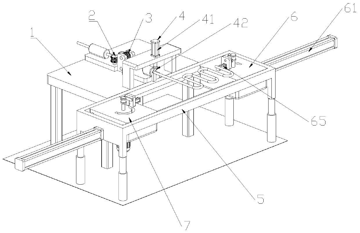
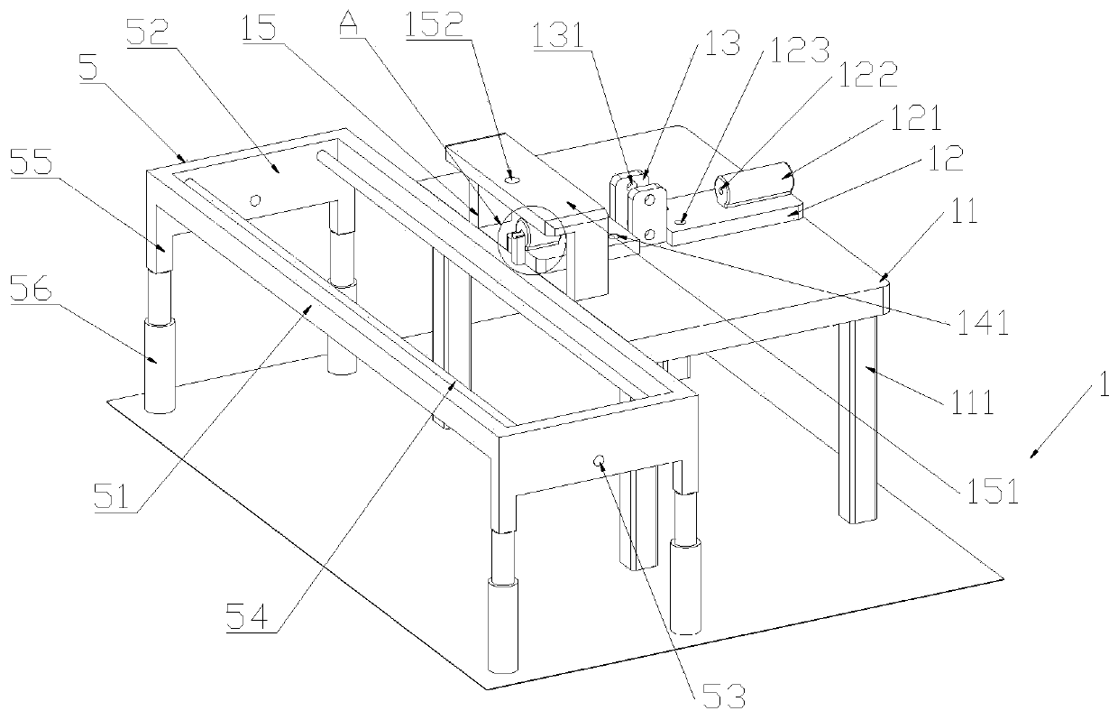
[0072] Insert the steel bar from the first guide hole 122, fit the steel bar through the annular slot 2342 on the transmission member 23, engage the steel bar with the engaging teeth 2341, and drive the steel bar to run in the equipment through the rotation of the first motor 21. The steel bar is guided and transported by the guide wheel 31 .
[0073] The steel bar extends to one side of the second bracket 5 through the second guide hole 143, the first cylinder 61 drives the bending base 62 to move on the first guide rod 54, and the telescopic cylinder 56 drives the square frame body 51 to move upwards, so that the steel bar is located on the first guide rod 54. Between the first contact block 644 and the second contact block 661, the extruding member 66 is driven by the second cylinder 65 to extrude the steel bar, so that the steel bar is engaged between the second extrusion groove 645 and the third extrusion groove 662, and passes through the second extrusion groove 645 and t...
Embodiment 2
[0080] Use any one of the first bending forming device 6 and the second bending forming device 7 to perform bending work on the steel bar.
[0081] Insert the steel bar from the first guide hole 122, fit the steel bar through the annular slot 2342 on the transmission member 23, engage the steel bar with the engaging teeth 2341, and drive the steel bar to run in the equipment through the rotation of the first motor 21. The steel bar is guided and transported by the guide wheel 31 .
[0082] The steel bar extends to one side of the second bracket 5 through the second guide hole 143, the first cylinder 61 drives the bending base 62 to move on the first guide rod 54, and the telescopic cylinder 56 drives the square frame body 51 to move upwards, so that the steel bar is located on the first guide rod 54. Between the first contact block 644 and the second contact block 661, the extruding member 66 is driven by the second cylinder 65 to extrude the steel bar, so that the steel bar i...
PUM
 Abstract
Description
Claims
Application Information
 - R&D Engineer
- R&D Manager
- IP Professional
- Industry Leading Data Capabilities
- Powerful AI technology
- Patent DNA Extraction
Browse by: Latest US Patents, China's latest patents, Technical Efficacy Thesaurus, Application Domain, Technology Topic, Popular Technical Reports.
© 2024 PatSnap. All rights reserved.Legal|Privacy policy|Modern Slavery Act Transparency Statement|Sitemap|About US| Contact US: help@patsnap.com