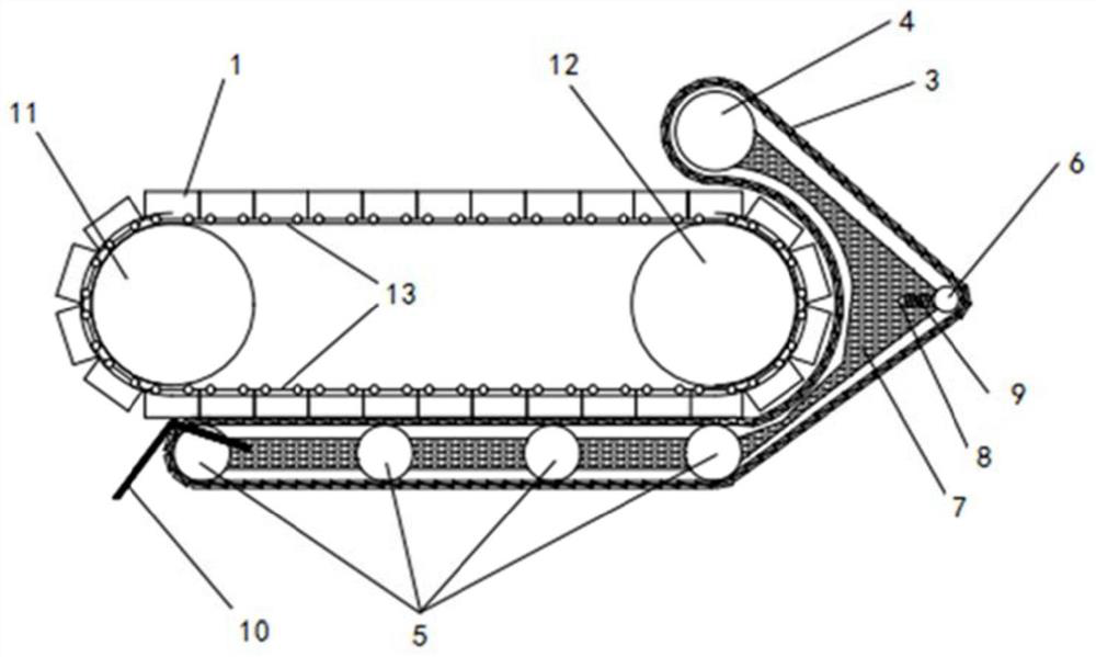
A high-utilization belt-type sintering machine
A belt-type sintering machine and utilization rate technology, applied in the furnace, furnace type, charge control and other directions, can solve the problems of difficult to carry out, incomplete sintering, and the requirement of increasing the exhaust air pressure, so as to reduce the number of trolleys and improve the The effect of smaller pores and increased running resistance
- Summary
- Abstract
- Description
- Claims
- Application Information
AI Technical Summary
Problems solved by technology
Method used
Image

Examples
Embodiment Construction
[0026] In order to enable those skilled in the art to better understand the technical solutions of the present application, the present invention will be further described in detail below in conjunction with specific embodiments and accompanying drawings.
[0027] The orientation terms such as up, down, left, right, front and rear in this application document are established based on the positional relationship shown in the drawings. If the drawings are different, the corresponding positional relationship may also change accordingly, so this should not be understood as limiting the scope of protection.
[0028] In the present invention, the terms "installation", "connection", "connection", "connection", "fixation" and so on should be understood in a broad sense, for example, it can be a fixed connection, a detachable connection, or an integrated Connection can also be mechanical connection, electrical connection or mutual communication, direct connection or indirect connection...
PUM
 Abstract
Description
Claims
Application Information
 - R&D
- Intellectual Property
- Life Sciences
- Materials
- Tech Scout
- Unparalleled Data Quality
- Higher Quality Content
- 60% Fewer Hallucinations
Browse by: Latest US Patents, China's latest patents, Technical Efficacy Thesaurus, Application Domain, Technology Topic, Popular Technical Reports.
© 2025 PatSnap. All rights reserved.Legal|Privacy policy|Modern Slavery Act Transparency Statement|Sitemap|About US| Contact US: help@patsnap.com