
Shock absorbing shaft seat device for motor suspension

A shock-absorbing shaft and vertical shock-absorbing technology, applied in electromechanical devices, transmission devices driven by motors, springs/shock absorbers, etc., can solve the problem of increasing inspection frequency, reducing the stability and reliability of linear motor installation, increasing Maintenance costs, etc.

Active Publication Date: 2020-01-24
CRRC CHANGCHUN RAILWAY VEHICLES CO LTD
View PDF11 Cites 0 Cited by
  • Summary
  • Abstract
  • Description
  • Claims
  • Application Information

AI Technical Summary

Problems solved by technology

[0006] In order to solve the problem that the existing shaft-suspended motor suspension method in which the linear motor is directly hung on the axle of the train will constrain the freedom of movement of the bogie wheel to the axle, the vibration of both the frame and the axle will act directly in the form of rigid transmission. On the linear motor, which affects the service life of the three; and the suspension structure of the linear motor with elastic shock absorption function is to suspend the linear motor on the frame beam through a series of springs, and only through a series of springs with a large length In order to hang down from the frame beam for a long enough distance, so that the air gap value between the linear motor suspended by the primary spring and the induction plate on its special rail is within the parameter range specified by the design, but the length value is relatively large The first series of springs weakens the stiffness parameter of the spring against its own radial swing, resulting in a greater swing degree of freedom for the linear motor suspended by the first series of springs, thereby increasing the swing and vibration amplitude of the linear motor and reducing the linear motor. The stability and reliability of the installation will further shorten the maintenance period and increase the inspection frequency, increase the maintenance cost, and negatively affect the safety of train operation. The invention provides a shock absorber for motor suspension Shaft seat device

Method used


Image

  • Shock absorbing shaft seat device for motor suspension
  • Shock absorbing shaft seat device for motor suspension
  • Shock absorbing shaft seat device for motor suspension

Examples


Embodiment Construction

[0033] The present invention will be described in further detail below in conjunction with the accompanying drawings.

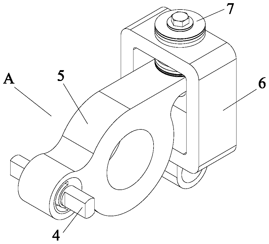
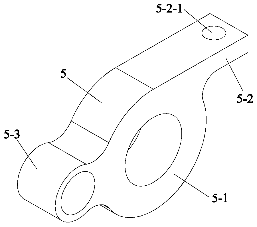
[0034] like Figure 1 to Figure 11 As shown, the shock-absorbing shaft seat device for motor suspension of the present invention includes a rubber node 4 as a horizontal elastic shaft part, an eccentric wheel axle sleeve 5, a vertical bearing suspension 6 and a vertical shock-absorbing pin mechanism 7, and the eccentric The wheel axle sleeve seat 5 includes an integrally formed axle sleeve 5-1, a bearing hanger connecting plate 5-2 and a rubber node sleeve 5-3, and the bearing hanger connecting plate 5-2 is along the tangent line of the outer diameter of the axle sleeve 5-1. The direction is connected with it, and the far end of the bearing hanger connecting plate 5-2 is provided with a vertical connecting plate through hole 5-2-1, and the axis of the connecting plate through hole 5-2-1 is aligned with the axis of the axle sleeve 5-1. The different planes ar...


PUM


Abstract

The invention provides a shock absorbing shaft seat device for motor suspension and belongs to the field of a suspending device for a motor of a rail vehicle. The shock absorbing shaft seat device comprises a rubber node, an eccentric wheel axle sleeve seat, a vertical bearing lifting seat and a vertical shock absorbing pin mechanism, wherein the rubber node acts as a horizontal elastic shaft component; and the eccentric wheel axle sleeve seat comprises an axle sleeve, a bearing lifting seat connecting plate and a rubber node shaft sleeve which are formed integrally. The shock absorbing shaftseat device provided by the invention makes a motor housing base plate obtain symmetric stability mechanically structurally, makes the stress distribution between an axle and the motor housing base plate be more reasonable, also achieves the effects of optimizing the structural balance performance, reducing fatigue losses of materials and prolonging the service life of equipment, and makes the parameter range of the value of an air gap from a linear motor suspended at a special linear motor lifting seat to a sensing plate on a special rail for the linear motor completely meet the optimal design requirements of the linear motor.

Description

technical field [0001] The invention belongs to the field of rail vehicle motor suspension devices, and in particular relates to a shock-absorbing axle seat device for motor suspension. Background technique [0002] The rail train based on the linear motor as the driving device changes the power of the vehicle from the rotational adhesion drive to the motor linear drive, which improves the climbing ability of the rail vehicle and greatly improves the vehicle's ability to adapt to the terrain. The special rail for the linear motor of this type of train is provided with an induction plate, and a small enough air gap must be kept between the linear motor and the induction plate to improve the driving force of the linear motor. This type of rail vehicle not only inherits the technical advantages of the conventional steel wheel-rail rail transit system, but also avoids the technical weaknesses of rubber wheel monorail and other transportation systems, so it can be widely used in ...

Claims


Application Information

Patent Timeline
Patent Type & Authority Applications(China)
IPC IPC(8): F16F15/08F16F15/126B61C9/50H02K5/24
CPCB61C9/50F16F15/08F16F15/126H02K5/24
Inventor 陆海英薛文根王文华
Owner CRRC CHANGCHUN RAILWAY VEHICLES CO LTD
Learn More