Device for quickly extracting silkworm cocoons
A technology of removing device and silkworm cocoon, applied in animal husbandry and other directions, can solve the problems of poor blood flow of fingers, slow removal speed, affecting the speed of removal, etc., and achieve the effect of avoiding the offset of the cocoon frame
- Summary
- Abstract
- Description
- Claims
- Application Information
AI Technical Summary
Problems solved by technology
Method used
Image
Examples
Embodiment 1
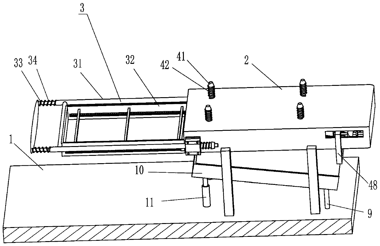
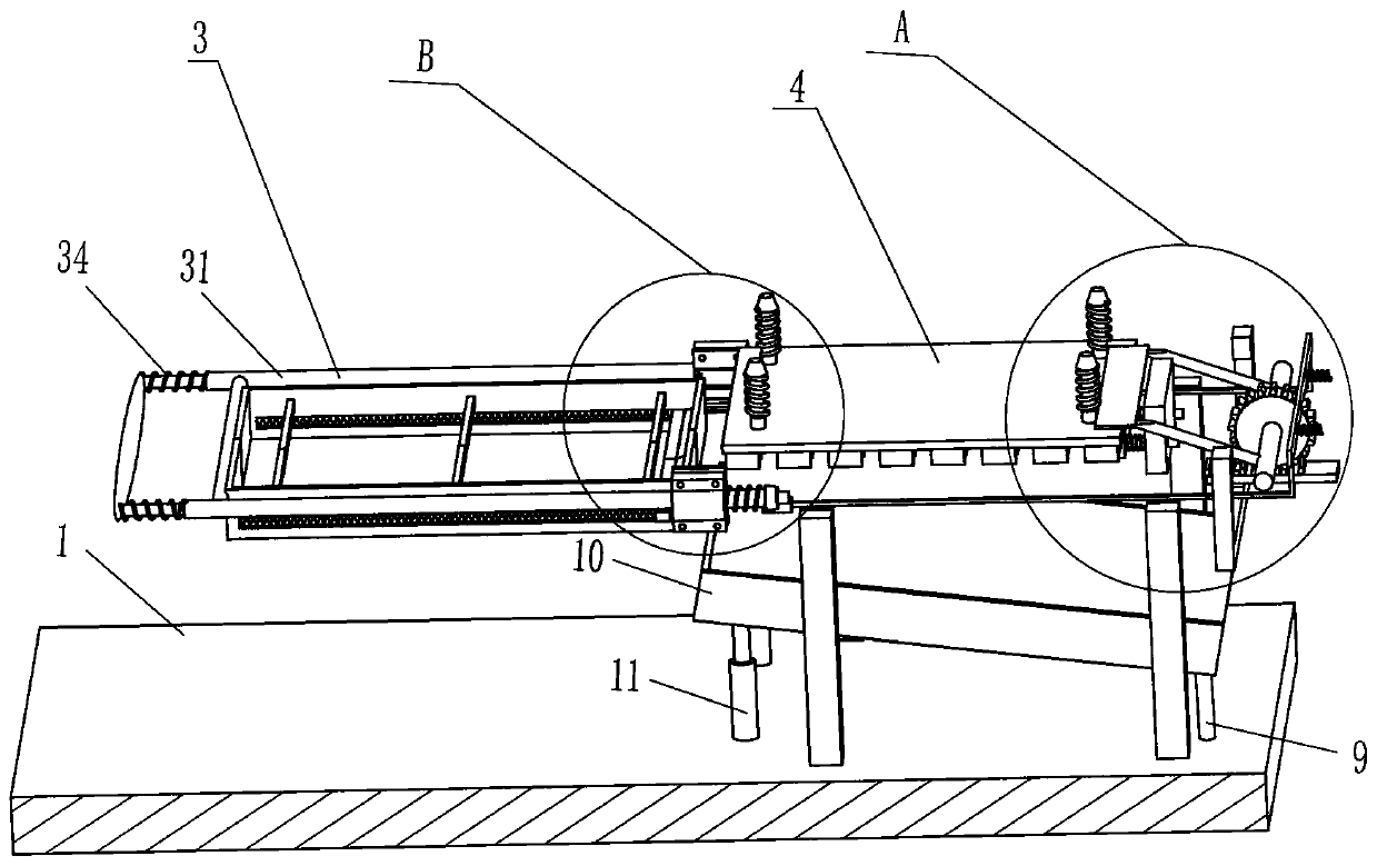
[0023] A kind of silkworm cocoon quick taking-out device, such as Figure 1-3 As shown, it includes a base 1, a frame body 2, a pushing device 3 and a pushing device 4. A frame body 2 is installed on the base 1. The left side and the lower side of the frame body 2 are open, and the frame body 2 is of sliding A pushing device 3 is provided, and the pushing device 3 is used for placing and pushing the cocooning frame into the frame body 2, and a pushing device 4 is arranged inside the frame body 2, and the pushing device 4 is used for pushing out silkworm cocoons.
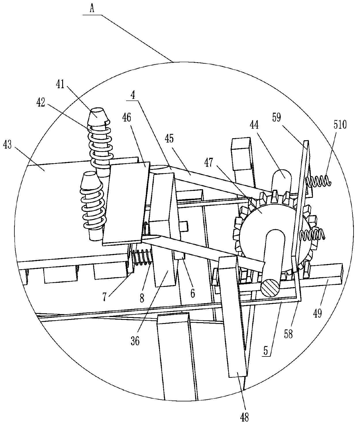
[0024] The pushing device 3 includes a hollow slide bar 31, a placement frame 32, a U-shaped slide bar 33, a first spring 34, a second spring 35 and a limit plate 36, and the front and rear sides of the frame body 2 are slidingly provided with hollow slide bars. 31, the hollow sliding bar 31 is fixedly connected with a placing frame 32 for placing the cocooning frame, the placing frame 32 can be moved to the inside o...
Embodiment 2
[0028] On the basis of Example 1, such as Figure 1-5As shown, a scraper device 5 is also included, and the scraper device 5 includes a scraper 52, a fourth spring 53, a limit block 55, a fifth spring 56, an L-shaped inclined rod 58, a movable plate 59 and a sixth spring 510 There are horizontal chute 51 on both sides of the front and back of the placement frame 32, and a scraper 52 for scraping off silkworm cocoons is slidably provided in the horizontal chute 51. Four springs 53, vertical chute 54 is provided on the front and rear sides of the left part of the frame body 2, and a limit block 55 is slidably provided in the vertical chute 54, and the limit block 55 contacts and cooperates with the scraper 52 A fifth spring 56 is connected between the limiting block 55 and the vertical chute 54, and the fifth spring 56 is in a stretched state. There is a chute 57 on the right side of the limiting block 55, and the frame body 2 slides The formula is provided with an L-shaped inc...
Embodiment 3
[0031] On the basis of Example 2, such as Figure 1-5 As shown, it also includes a horizontal slide bar 6, a rubber plate 7 and a seventh spring 8. The limit plate 36 is slidably provided with a horizontal slide bar 6, and the left end of the horizontal slide bar 6 is equipped with a rubber plate 7. The rubber plate A seventh spring 8 is connected between 7 and the limiting plate 36 .
[0032] It also includes a fixed rod 9, a lower hopper 10 and a telescopic rod 11. A telescopic rod 11 is installed in the middle of the base 1. The telescopic rod 11 is provided with a lower hopper 10 in a rotating manner, and a fixed rod is installed on the right side of the base 1. 9. The top end of the fixed rod 9 is connected to the right side of the lower hopper 10 in a rotational manner.
[0033] When the placement frame 32 moves to the right to contact with the rubber plate 7, under the action of the horizontal slide bar 6 and the seventh spring 8, the rubber plate 7 can buffer and shoc...
PUM
 Abstract
Description
Claims
Application Information
 - R&D
- Intellectual Property
- Life Sciences
- Materials
- Tech Scout
- Unparalleled Data Quality
- Higher Quality Content
- 60% Fewer Hallucinations
Browse by: Latest US Patents, China's latest patents, Technical Efficacy Thesaurus, Application Domain, Technology Topic, Popular Technical Reports.
© 2025 PatSnap. All rights reserved.Legal|Privacy policy|Modern Slavery Act Transparency Statement|Sitemap|About US| Contact US: help@patsnap.com


