Eureka AIR delivers breakthrough ideas for toughest innovation challenges, trusted by R&D personnel around the world.

Connecting node placement method and product for combined lintel model and combined upright column model

A technology for connecting nodes and models, applied in geometric CAD and other directions, can solve problems such as low efficiency

Active Publication Date: 2020-01-17
久瓴(江苏)数字智能科技有限公司
View PDF3 Cites 2 Cited by
  • Summary
  • Abstract
  • Description
  • Claims
  • Application Information

AI Technical Summary

Problems solved by technology

[0004] However, the traditional method of manually placing the joints between the composite lintel and the composite column is inefficient

Method used

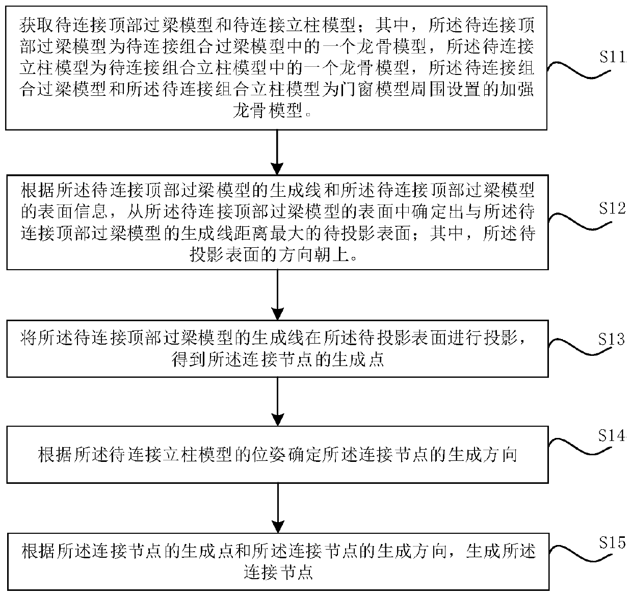
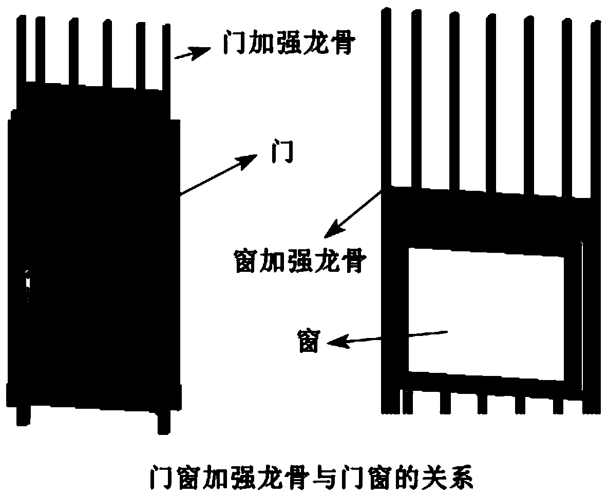

Image

  • Connecting node placement method and product for combined lintel model and combined upright column model
  • Connecting node placement method and product for combined lintel model and combined upright column model
  • Connecting node placement method and product for combined lintel model and combined upright column model

Examples


Embodiment Construction

[0061] In order to make the purpose, technical solution and advantages of the present application clearer, the present application will be further described in detail below in conjunction with the accompanying drawings and embodiments. It should be understood that the specific embodiments described here are only used to explain the present application, and are not intended to limit the present application.

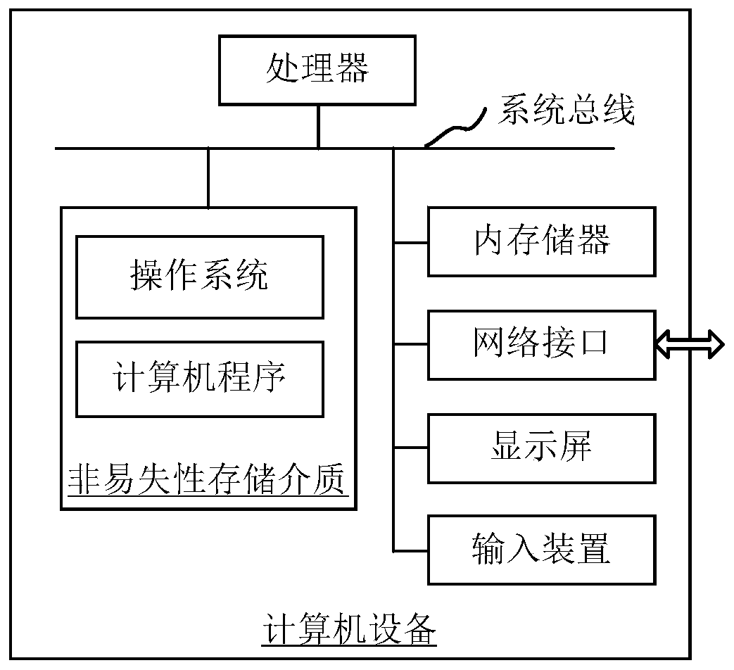
[0062] The connection node placement method of the composite lintel model and the composite column model provided in the embodiment of this application can be applied to figure 1 computer equipment shown. The computer device includes a processor, a memory, a network interface, a database, a display screen and an input device connected through a system bus. Wherein, the processor of the computer device is used to provide calculation and control capabilities. The memory of the computer device includes a non-volatile storage medium and an internal memory. The non-volatile ...


PUM


Abstract

The invention relates to a connecting joint placement method and product for a combined lintel model and a combined stand column model. The method comprises the steps that a to-be-connected top lintelmodel and a to-be-connected stand column model are acquired; according to the generation line of the to-be-connected top lintel model and the surface information of the to-be-connected top lintel model, determining a to-be-projected surface having the largest distance with the generation line of the to-be-connected top lintel model from the surfaces of the to-be-connected top lintel model; projecting a generation line of the to-be-connected top lintel model on the to-be-projected surface to obtain a generation point of the connection node; determining a generation direction of the connectionnode according to the pose of the stand column model to be connected; and generating the connection node according to the generation point of the connection node and the generation direction of the connection node. By adopting the method, the placement efficiency of the connection nodes can be improved.

Description

technical field [0001] The present application relates to the technical field of computer equipment, in particular to a method and product for placing connection nodes of a composite lintel model and a composite column model. Background technique [0002] With the rapid development of computer technology, automatic aided design has been widely used in various industries. [0003] Generally, in the field of architectural design, people use automated design software to design buildings. Usually, when aiming at two solid models that need to be connected, the designer often needs to observe the design model, and subjectively judge the parts that need to be connected between the solid models, and then select the setting position of the connecting node to generate the connecting node by operating the computer equipment . For example, when setting connectors between a composite lintel and a composite column, the designer first needs to find out the model of the composite lintel a...

Claims


Application Information

Patent Timeline
IPC IPC(8): G06F30/13
CPCY02P90/30
Inventor 尤勇敏其他发明人请求不公开姓名
Owner 久瓴(江苏)数字智能科技有限公司
Why Eureka
Eureka Blog
Learn More