
A turning control method, device and machining lathe with variable feed speed

A technology of feed speed and control method, applied in the direction of program control, digital control, general control system, etc., can solve problems such as affecting the reliability of parts

Active Publication Date: 2020-10-16
XIAN FASHITE AUTOMOBILE TRANSMISSION CO LTD
View PDF5 Cites 0 Cited by
  • Summary
  • Abstract
  • Description
  • Claims
  • Application Information

AI Technical Summary

Problems solved by technology

[0004] The object of the present invention is to provide a turning control method, device and processing lathe with variable feed speed, to solve the problem that the turning method in the prior art directly increases the feed speed of the tool at the position where continuous processing is required, resulting in intermittent Obvious tool marks will be formed at the connection position between the processing part and the continuous processing part, which will affect the reliability of the part

Method used


Image

  • A turning control method, device and machining lathe with variable feed speed
  • A turning control method, device and machining lathe with variable feed speed
  • A turning control method, device and machining lathe with variable feed speed

Examples


Embodiment 1

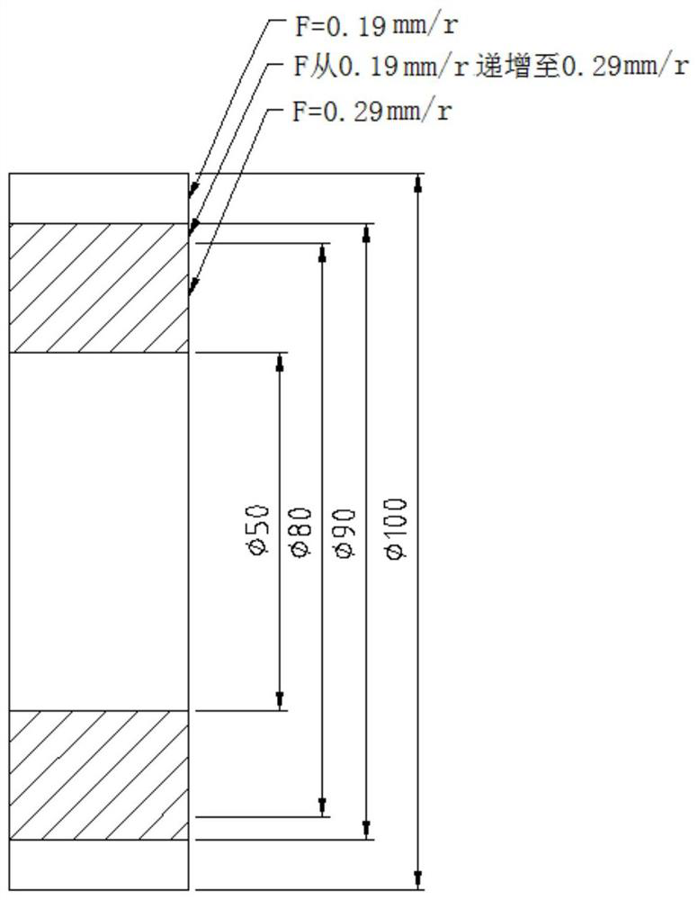
[0083] This embodiment provides a turning control method with variable feed speed, which is used for turning the surface of the part to be processed, and is performed according to the following steps:

[0084] Before performing the following steps, first select the tool according to the actual situation, from the tool material, machine holder blade form, and tool nose arc angle. In this example, the workpiece is heat-hardened low-carbon alloy steel, and the material is 20CrMnTiH, so the blade material is selected as CBN blade. There is no interference in the end face processing, so the CNGA120408 standard blade with good strength and stable clamping is selected.

[0085] Secondly, the Taylor formula to determine the tool durability can be used to determine whether the method of increasing the feed rate at a constant speed can not only ensure the quality, but also improve the processing efficiency. When a0, it is necessary to calculate the minimum feed speed that meets the takt...

Embodiment 2

[0140] This embodiment provides a turning control device with variable feed speed, which is used for turning the surface of the part to be processed, including a partition module and a turning control module:

[0141] The partition module is used to partition the surface of the part to be processed according to the processing requirements of the surface of the part to be processed to obtain multiple processing areas; the processing requirements include different roughness processing or continuous-intermittent processing;

[0142] The turning control module is used for turning two adjacent processing areas, specifically including the variable speed area determination sub-module and the vehicle speed control sub-module;

[0143] The variable speed area determination sub-module is used to determine the variable speed area at the junction of two adjacent processing areas to obtain the variable speed area;

[0144] Take the area other than the variable speed area in the processing ...

Embodiment 3

[0168] This embodiment provides a processing lathe, including the turning control device with variable feed speed in the second embodiment.

[0169] In this embodiment, a processing lathe is disclosed, which includes a turning control device with variable feed speed, so that during the processing of the processing lathe, the surface roughness of the processed part is guaranteed, and the processing speed is improved. Tool life in lathes.


PUM


Abstract

The invention discloses a turning control method and a device with a variable feed speed and a machining lathe. The turning control method comprises steps of determining a speed-variable machining area from two adjacent machining areas to obtain a speed-variable area; using remaining areas in the machining areas except for the speed-variable area as speed-constant areas to obtain two speed-constant areas, obtaining a constant feed speed in each speed-constant area; perform turning by using the constant feed speed corresponding to the current speed-constant area in the speed-constant areas as acurrent turning speed; and performing turning by adjusting a feed speed in a speed-variable manner in the speed-variable area as a current turning speed. The turning control method and the device with the variable feed speed provided by the invention set the speed-variable area ans slowly adjust the feed speed in the speed-variable manner in the speed-variable area to eliminate blade grains generated by sudden increase of feed speed, improving surface machining precision of parts and enhancing reliability of parts.

Description

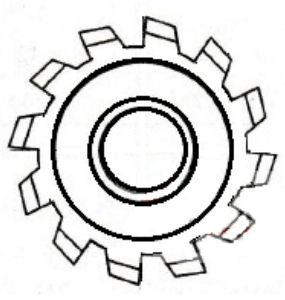
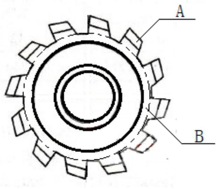
technical field [0001] The invention relates to a turning method and device, in particular to a turning control method, device and processing lathe with variable feed speed. Background technique [0002] In the process of continuous machining of the same plane or curved surface, there are often situations such as different surface roughness requirements and different processing conditions (such as intermittent and continuous cutting conditions), such as figure 1 For the toothed parts shown, the toothed part needs to be processed intermittently, while the middle part of the part needs to be processed continuously. In processing the toothed part, a lower tool feed speed is generally required for turning. If they are all processed at this low speed , will affect the processing efficiency. [0003] Therefore, in order to improve the processing efficiency, the existing turning control method will directly increase the feed speed of the tool in the part that needs continuous proc...

Claims


Application Information

Patent Timeline
Patent Type & Authority Patents(China)
IPC IPC(8): G05B19/416B23F15/00
CPCB23F15/00G05B19/416G05B2219/36346
Inventor 刘欣严鉴铂赵艳文李鹏
Owner XIAN FASHITE AUTOMOBILE TRANSMISSION CO LTD
Learn More