Compact broadband spectral imaging optical system
A spectral imaging and optical system technology, applied in the field of spectral imaging optical system, wide-band light and small spectral imaging optical system, can solve the problems of difficult correction of aberrations, increase of working band, etc., to improve imaging quality, increase correction ability, improve Effect of Aberration Correction Capability
- Summary
- Abstract
- Description
- Claims
- Application Information
AI Technical Summary
Problems solved by technology
Method used
Image
Examples
Embodiment 1
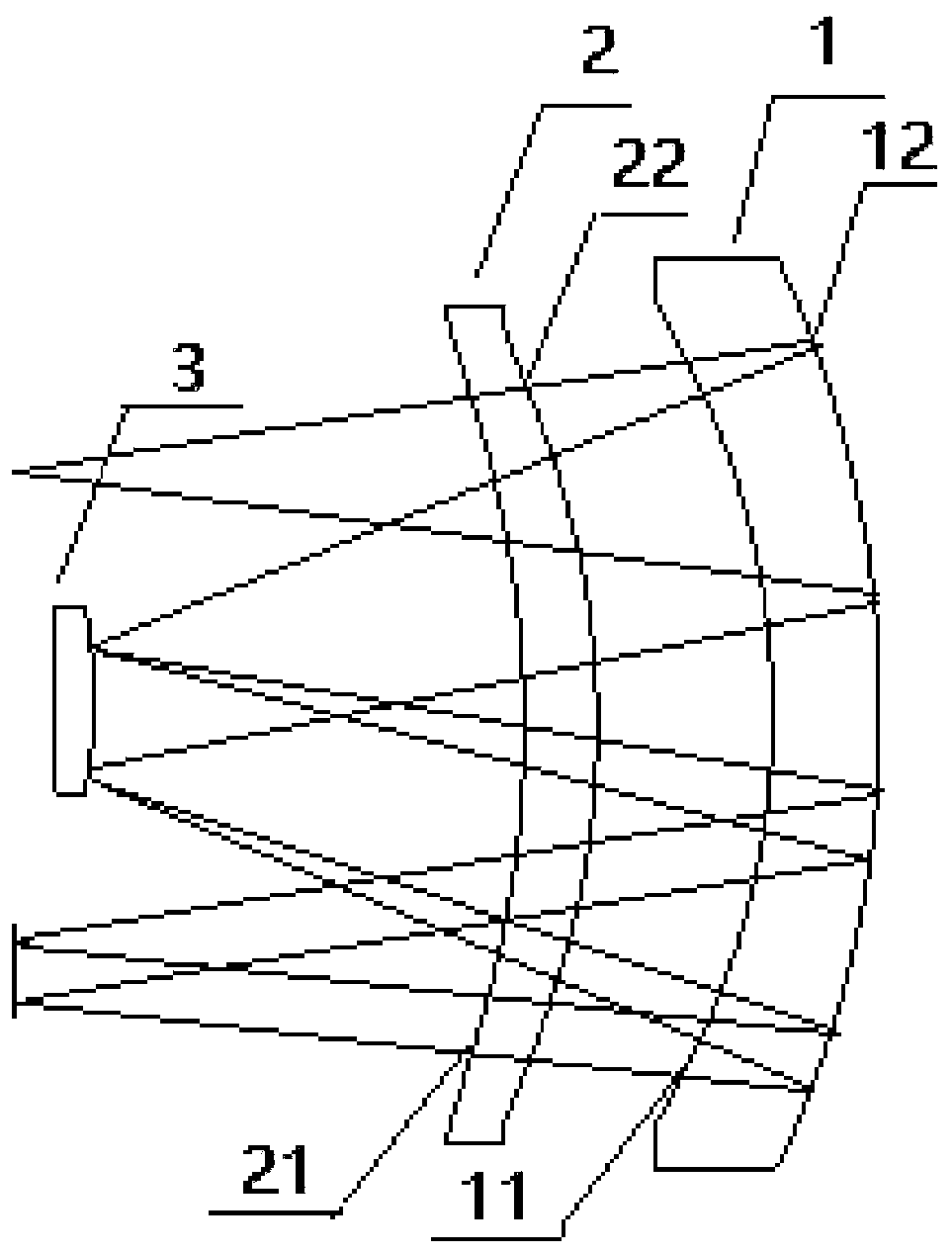
[0026] Such as figure 1 As shown, a compact broadband spectral imaging optical system includes an immersion primary mirror 1, a correction lens 2 and a convex grating 3; the immersion primary mirror is set as an optical element with positive power, which includes an immersion primary mirror Mirror first surface 11 and submerged primary mirror second surface 12, wherein the submerged primary mirror first surface is the object side and is set as a refraction surface, and the submerged primary mirror second surface is a reflective surface and is bent toward the object side; The convex grating is set as a reflective grating structure; the light emitted by the object surface is refracted from the first surface of the submerged primary mirror to the second surface of the submerged primary mirror after passing through the correction lens, and the light reflected by the second surface of the submerged primary mirror After passing through the correction lens, it is reflected by the con...
Embodiment 2
[0028] The radius of curvature R11 of the first surface of the submerged primary mirror and the radius of curvature R12 of the second surface of the submerged primary mirror meet the following conditions: 1.3<R12 / R11<1.42; the correction lens is set as an optical element with negative power, It includes the first surface of the correction lens and the second surface of the correction lens, the radius of curvature R21 of the first surface of the correction lens and the radius of curvature R22 of the second surface of the correction lens satisfy the following conditions: 0.77<R22 / R21<0.82; the surface curvature of the convex grating The radius R3 and the second surface curvature radius R12 of the submerged primary mirror satisfy the following condition: 0.38<R3 / R12<0.43.
[0029] The preferred solution: the immersion primary mirror 1 is an optical element with positive refractive power, which is used for converging the incident light beam on the object side and the outgoing light...
Embodiment 3
[0037] A compact broadband spectral imaging optical system based on the first embodiment, the optical system F / # is 3.4, its field of view is 28mm, the working waveband covers 400-2500nm, and the spectrum width is 4.2mm; the submerged primary mirror The specific parameters of the correction lens and the convex grating are shown in the table;
[0038]
[0039] In the embodiment, the distance between the submerged primary mirror and the correction lens is 6.113mm, and the distance between the correction lens and the convex grating is 23.04mm.
[0040] In an embodiment, the first surface of the correction lens, the second surface of the correction lens, and the first surface of the submerged primary mirror are aspheric surfaces. Its aspheric system is shown in the table below.
[0041] Coefficient B Coefficient C Coefficient D Correcting lens first surface 21 4.10e-011 3.49e-013 1.20e-016 Correcting lens second surface 22 1.72e-010 2.01e-013 2....
PUM
 Abstract
Description
Claims
Application Information
 - R&D
- Intellectual Property
- Life Sciences
- Materials
- Tech Scout
- Unparalleled Data Quality
- Higher Quality Content
- 60% Fewer Hallucinations
Browse by: Latest US Patents, China's latest patents, Technical Efficacy Thesaurus, Application Domain, Technology Topic, Popular Technical Reports.
© 2025 PatSnap. All rights reserved.Legal|Privacy policy|Modern Slavery Act Transparency Statement|Sitemap|About US| Contact US: help@patsnap.com


