Denitrification filter tank for reducing carbon source consumption and operation method thereof
A denitrification filter, carbon source consumption technology, applied in the direction of chemical instruments and methods, water treatment parameter control, special treatment goals, etc., can solve the problems of high nitrogen consumption, affecting the efficiency of sewage filtration and treatment, etc., to achieve strong energy, The effect of improving utilization rate and improving processing efficiency
- Summary
- Abstract
- Description
- Claims
- Application Information
AI Technical Summary
Problems solved by technology
Method used
Image

Examples
Embodiment 1
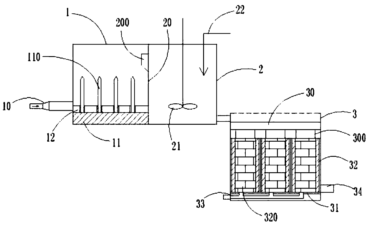
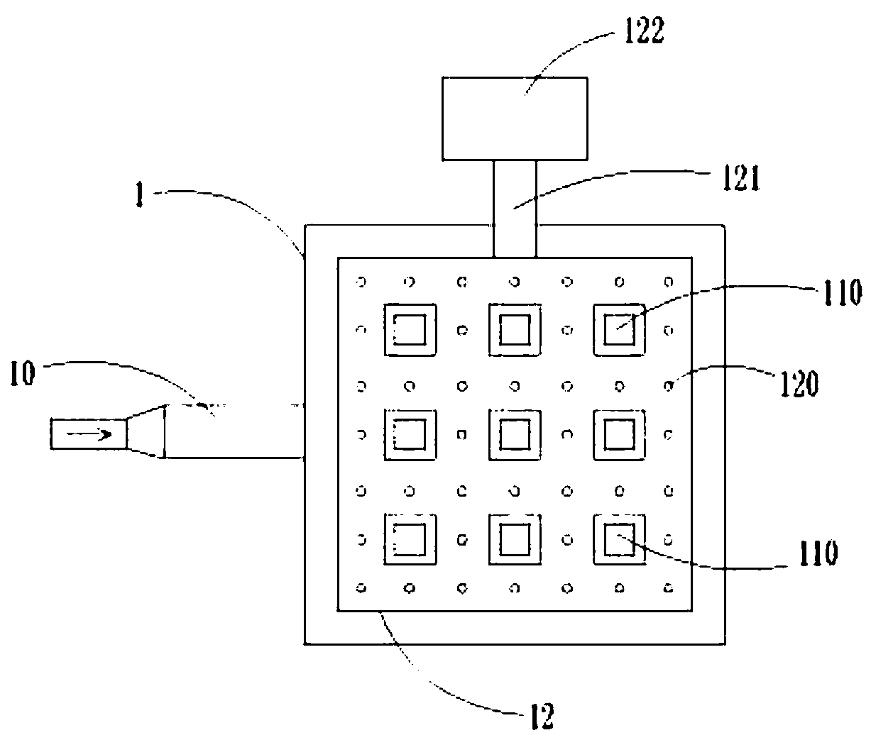
[0030] Embodiment 1: A kind of denitrification filter tank that reduces carbon source consumption, comprises ultrasonic treatment tank 1, carbon source dosing tank 2 and denitrification filter tank 3, is connected with pipe diameter change section 10 on the ultrasonic treatment tank 1, pipe diameter The changing section 10 is a tubular structure with a thin front end and a thick rear end; an ultrasonic generator 11 is provided at the inner bottom of the ultrasonic treatment pool 1, the working frequency of the ultrasonic generator 11 is 25KHZ, and the power density of the ultrasonic generator 11 is greater than 0.35W / cm 2 , the cavitation effect of ultrasonic waves makes it produce a large number of small bubbles when it acts on sewage, and local tensile stress appears in the water body to form negative pressure, so that the oxygen originally dissolved in sewage is supersaturated and escapes from the sewage to become small bubbles; in addition, due to The ultrasonic frequency i...
Embodiment 2
[0038] Embodiment 2: the difference between embodiment 2 and embodiment 1 is: the sewage treatment capacity of denitrification filter 3 is 20,000 tons / day, and the single cell filter size L * B = 36.58m * 4.27m, altogether 1 Grid, the size of the head is changed from DN400 to DN600, the ratio is 1.5, the volume of the ultrasonic treatment tank 1 is L×B×H=2m×2m×2m, and the distance between the ultrasonic conducting rods 110 installed at the bottom of the vertical ultrasonic treatment tank 1 is 0.4m , the distance from the pool wall is 0.4m, and a total of 16 are installed at the bottom of the pool; the transmission power of the ultrasonic generator 11 is set at 1700W, the height of the lower edge of the water outlet is 1.6m, and the residence time of the sewage is 27.65s; the carbon source dosing pool The volume of 2 is the same as that of ultrasonic treatment tank 1. The dosing port of carbon source dosing pipe 22 is fixed close to the wall of carbon source dosing tank 2 at a h...
Embodiment 3
[0039] Embodiment 3: The difference between embodiment 3 and embodiment 1 is: the sewage treatment capacity of the denitrification filter 3 is 100,000 tons / day, and the size of the single cell filter is L×B=25.50m×4.26m, a total of 8 grid, the size head is changed from DN400 to DN800, and the ratio is 2. The volume of the ultrasonic treatment pool 1 is L×B×H=3m×3m×3m. The ultrasonic conductive rods 110 installed at the bottom of the vertical ultrasonic treatment pool 1 are spaced at 0.3m intervals, and the distance from the pool wall is 0.3m. A total of 81 rods are installed. , the transmission power of the ultrasonic generating device 11 is set to 990W, the height of the lower edge of the water outlet is 2.6m, the residence time of the sewage is 20.22s, the volume of the carbon source dosing pool 2 is the same as that of the ultrasonic treatment pool 1, and the carbon source dosing pipe 22 The dosing port is fixed close to the wall of the carbon source dosing pool 2 at a heig...
PUM
 Abstract
Description
Claims
Application Information
 - R&D
- Intellectual Property
- Life Sciences
- Materials
- Tech Scout
- Unparalleled Data Quality
- Higher Quality Content
- 60% Fewer Hallucinations
Browse by: Latest US Patents, China's latest patents, Technical Efficacy Thesaurus, Application Domain, Technology Topic, Popular Technical Reports.
© 2025 PatSnap. All rights reserved.Legal|Privacy policy|Modern Slavery Act Transparency Statement|Sitemap|About US| Contact US: help@patsnap.com