


Quick Research
Generate reliable direction feasibility study reports for your R&D in just a few steps.

Technical Q&A
Discover and master advanced knowledge NOW. Basics, ideas, possibilities, all at once.

Find Solutions
As an expert in R&D theories, this can generate solutions to your technical problems instantly.

Evaluate Feasibility
Analyze your overall solution with one click, know your potential R&D risks in advance.

Monitor Landscape
Get weekly tech updates, stay abreast of the latest tech innovations and key insights.
A buffer distribution box, dual-motor cooling system and electric vehicle
A cooling system and dual-motor technology, applied in the direction of electric power units, power units, vehicle components, etc., can solve problems such as inconsistent cooling effects of motors, and achieve the effects of low maintenance costs, low manufacturing costs, and high reliability
- Summary
- Abstract
- Description
- Claims
- Application Information
AI Technical Summary
Problems solved by technology
Method used
Image


Examples
Embodiment 1
[0042] This embodiment discloses a dual-motor cooling system, which is applied to an electric vehicle and used to cool heat-generating components inside the electric vehicle.
[0043] The electric vehicle is driven by hub motor technology, and the electric vehicle includes two motors 1, and the two motors 1 are installed on two hubs at one end of the electric vehicle, such as two hubs on the front axle of the electric vehicle. The motor 1 is the main heating component inside the electric vehicle, and the dual motor 1 cooling system in this embodiment is mainly used to cool the motor 1 .
[0044] The setting of two motors 1, in addition to providing sufficient driving force, is also beneficial to the layout of the frame and chassis, because a single driving device also needs to set up an additional transmission mechanism to transmit the driving force to the two hubs, and the two hubs are respectively connected to each other. If one motor 1 is assembled, the transmission mechani...
Embodiment 2
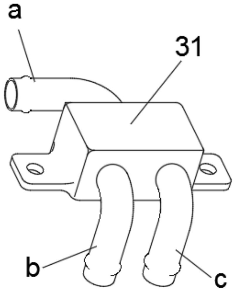
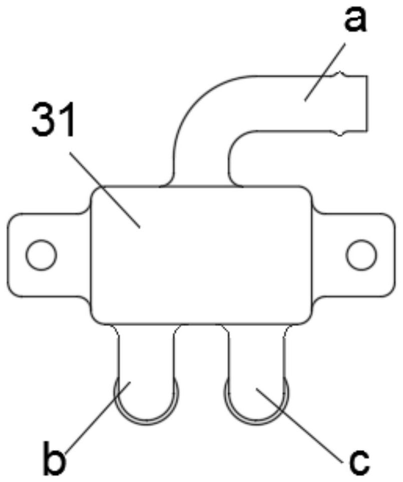
[0064] see Figure 1 to Figure 3 , the present embodiment provides a dual-motor 1 cooling system, which includes a cooling water tank 2, a water pump 4, two buffer distribution boxes, two motors 1 and a four-in-one controller 5.
[0065] The structures and connections of the cooling water tank 2, water pump 4, two buffer distribution boxes, two motors 1 and a four-in-one controller 5 are consistent with those in Embodiment 1, the differences are:
[0066] The dual motor 1 cooling system also includes an expansion tank 6 , an emptying pipeline 7 and a water return pipeline 8 .
[0067] During the actual assembly of electric vehicles, since the assembly position of the four-in-one controller 5 is higher than that of the motor 1, some places in the pipeline of the cooling circuit 100 need to reserve elbows as vibration buffers. In this embodiment , such elbows are reserved near the four-in-one controller 5 and near the two motors 1 . The bent pipe in the pipeline system changes...
Embodiment 3
[0075] see Figure 1 to Figure 4 , the present embodiment provides a dual motor 1 cooling system, which includes a cooling water tank 2, a water pump 4, an expansion tank 6, two buffer distribution boxes, two motors 1 and a four-in-one controller 5.
[0076] The structure and connection relationship of the heat dissipation water tank 2, water pump 4, expansion water tank 6, two buffer distribution boxes, two motors 1 and a four-in-one controller 5 are consistent with the second embodiment, the difference is that:
[0077] The dual-motor 1 cooling system also includes a cooling fan 10 and a control module 11, and the air outlet surface of the cooling fan 10 faces the cooling water tank 2 (such as Figure 4 As shown), the cooling fan 10 is used to blow the cold wind from the outside to the cooling water tank 2 to force the cooling of the cooling water tank 2.
[0078] Both the motor 1 and the four-in-one controller 5 are provided with temperature sensors, and the temperature se...
PUM
 Abstract
Description
Claims
Application Information
 - R&D Engineer
- R&D Manager
- IP Professional
- Industry Leading Data Capabilities
- Powerful AI technology
- Patent DNA Extraction
Browse by: Latest US Patents, China's latest patents, Technical Efficacy Thesaurus, Application Domain, Technology Topic, Popular Technical Reports.
© 2024 PatSnap. All rights reserved.Legal|Privacy policy|Modern Slavery Act Transparency Statement|Sitemap|About US| Contact US: help@patsnap.com