High-pressure water pump

A technology for high-pressure water pumps and pump bodies, which is applied to pumps, pump components, variable capacity pump components, etc. It can solve the problems of reduced production efficiency, short service life, weight and volume, etc., and achieve high production efficiency and long service life Effect

Active Publication Date: 2016-01-27
TAIZHOU DAJIANG IND
View PDF7 Cites 0 Cited by
  • Summary
  • Abstract
  • Description
  • Claims
  • Application Information

AI Technical Summary

Problems solved by technology

[0002] Most of the current power sources of nail guns are compressed air. To use compressed air, there must be an air inlet pipe connected to the nail gun body. It is very inconvenient for the user to pull the air pipe. In addition, the compressed air exhausts noise when it is working. Relatively large, users often need to wear protective earplugs
Moreover, the compressed air must be provided by an air compressor. The air compressor has weight and volume, and it is very inconvenient to carry for decoration personnel.
And the air compressor also needs cost
In the prior art, there are also devices that use high-pressure water pumps to generate power, but most of them have a short service life and require frequent replacement of parts. There is also the problem of large differences in nailing force each time, which greatly reduces production efficiency.

Method used


Image

  • High-pressure water pump
  • High-pressure water pump
  • High-pressure water pump

Examples


Embodiment Construction

[0031] For ease of understanding, the technical solutions of the present invention are further specifically described below in conjunction with the accompanying drawings and through embodiments:

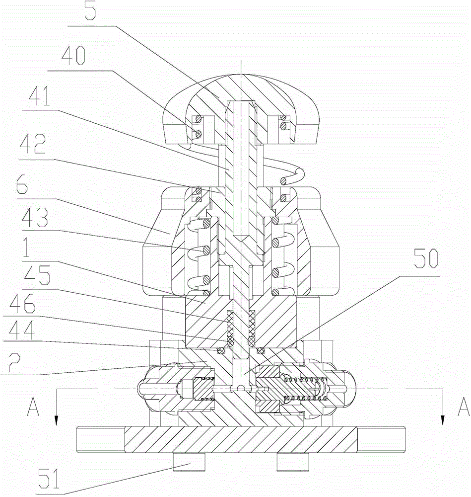
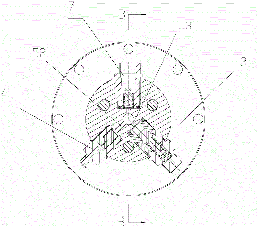
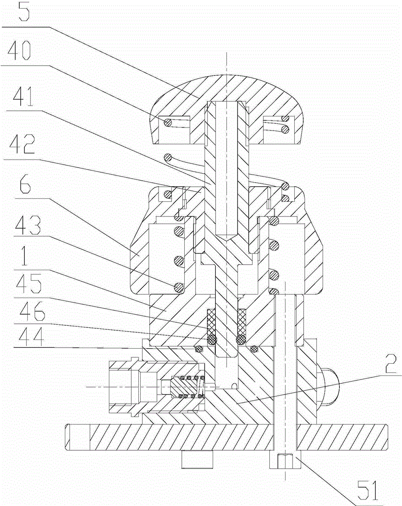
[0032] Such as Figure 1-Figure 8 As shown, a high-pressure water pump includes an upper pump body 1, a lower pump body 2, an outlet valve 3, an inlet valve 4, a plunger 41, a guide sleeve 42, a bushing 45, a seal 46, an inlet 52 and an outlet 53 and evacuation valve 7.

[0033] The upper pump body 1 and the lower pump body 2 are connected by connecting bolts 51, and a sealing ring 44 is arranged between the upper pump body 1 and the lower pump body 2, and the sealing ring 44 plays a role of sealing and preventing leakage.

[0034] The plunger 41 is sleeved in the upper pump body 1, and the upper end of the plunger 41 is threadedly connected with a percussion cap 5, and the upper end of the upper pump body 1 is provided with an adjustment cap 6, and the working displacement of the p...


PUM


Abstract

A high-pressure water pump comprises an upper pump body, a lower pump body, a water outlet valve, a water inlet valve, a plunger, a guide sleeve, a water inlet channel, a water outlet channel and a pump-out valve. The upper pump body is connected with the lower pump body through connection bolts, and a seal ring is arranged between the upper pump body and the lower pump body. The plunger is sleeved with the upper pump body, the upper end of the plunger is in threaded connection with a knocking cap, and an adjusting cap is arranged at the upper end of the upper pump body. A plunger reset spring is arranged between the knocking cap and the adjusting cap. A seal part is arranged between the upper pump body and the plunger. A working cavity is formed between the plunger and the upper pump body and/or the lower pump body. The water outlet valve, the water inlet valve and the pump-out valve are arranged on the lower pump body. The water inlet valve is connected with the working cavity through the water inlet channel. The water inlet valve is a one-way valve. The water outlet valve is connected with the working cavity through the water outlet channel. The pump-out valve is communicated with the working cavity by being connected with the lower pump body through threads. The high-pressure water pump can guarantee that the quantity of water ejected every time is equal and the intensity of driving a nail every time is the same.

Description

technical field [0001] The invention belongs to the field of mechanical devices, and in particular relates to a high-pressure water pump. Background technique [0002] Most of the current power sources of nail guns are compressed air. To use compressed air, there must be an air inlet pipe connected to the nail gun body. It is very inconvenient for the user to pull the air pipe, and the exhaust noise when the compressed air is working Relatively large, users often need to wear protective earplugs. Moreover, the compressed air must be provided by an air compressor. The air compressor has weight and volume, and it is very inconvenient to carry for decoration personnel. And the air compressor also needs cost. In the prior art, there are also devices that use high-pressure water pumps to generate power, but most of them have a short service life, require frequent replacement of parts, and have the problem of large differences in each nailing force, which greatly reduces product...

Claims


Application Information

Patent Timeline
Patent Type & Authority Applications(China)
IPC IPC(8): F04B13/00F04B53/02F04B53/10F04B53/00B25C1/04
CPCF04B13/00
Inventor 刘贵文杨明军黄锦全
Owner TAIZHOU DAJIANG IND
Why Eureka
Try Eureka