Under-liquid speed reducer perforating device

A technology of punching device and reducer, applied in feeding device, boring/drilling, drilling/drilling equipment and other directions, can solve the problems affecting the assembly efficiency and assembly quality of the reducer, low efficiency and high labor cost, Achieve the effect of improving assembly efficiency and assembly quality

Inactive Publication Date: 2020-01-17
WENZHOU POLYTECHNIC
View PDF11 Cites 1 Cited by
  • Summary
  • Abstract
  • Description
  • Claims
  • Application Information

AI Technical Summary

Problems solved by technology

However, the existing working operations of the upper shell and the lower shell are manually punched, which is inefficient and high in labor costs, and the hole position of the punched hole is also prone to deviation, which affects the assembly efficiency and assembly quality of the reducer.

Method used


Image

  • Under-liquid speed reducer perforating device
  • Under-liquid speed reducer perforating device
  • Under-liquid speed reducer perforating device

Examples


Embodiment Construction

[0028] The present invention will be described in further detail below in conjunction with the accompanying drawings.

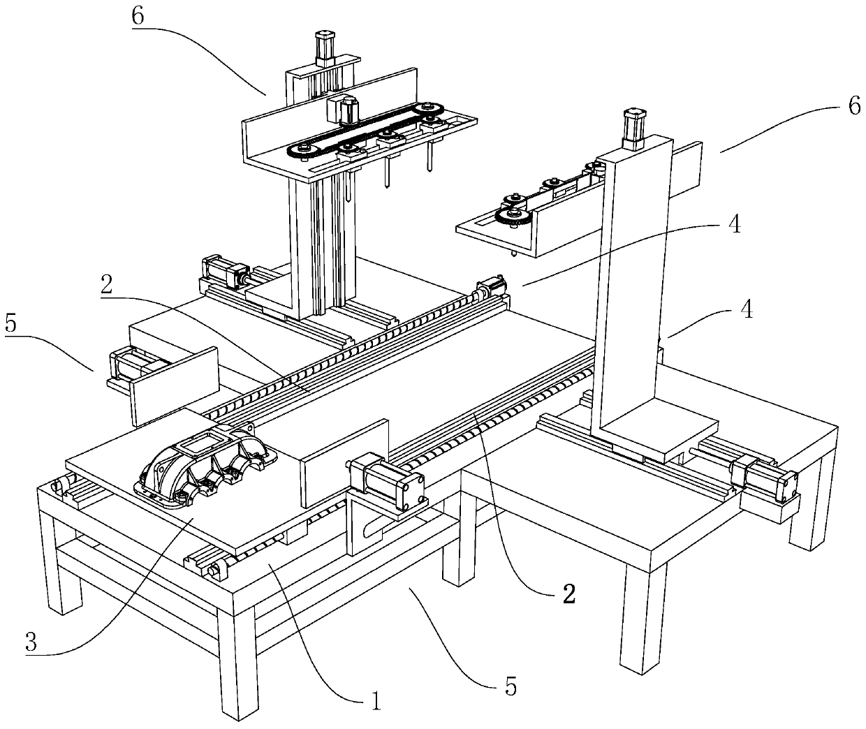
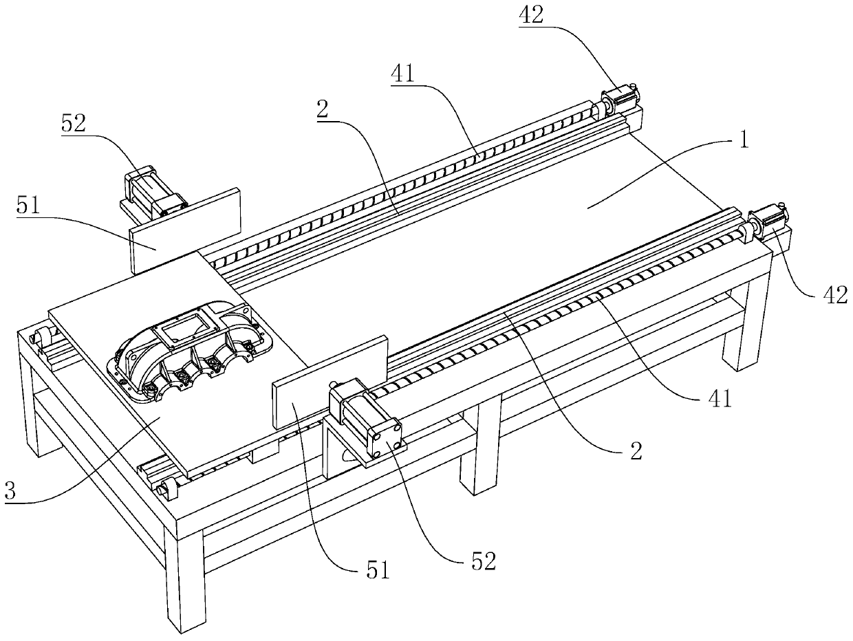
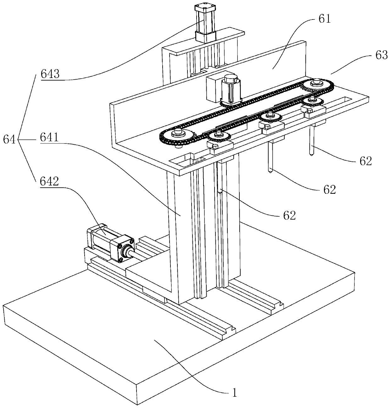
[0029] refer to Figure 1 to Figure 5 , a drilling device for a submerged reducer, comprising a base 1 and two first slide rails 2 fixedly arranged on the base 1, the two first slide rails 2 are arranged symmetrically and at intervals, and the two first slide rails 2 is slidably provided with a transfer seat 3 for placing workpieces to be processed, and the base 1 is provided with a first driving member 4 for driving the transfer seat 3 to reciprocate and slide. Both sides of the base 1 corresponding to the sliding direction of the first slide rails 2 are provided with an alignment member 5 for aligning the workpiece on the transfer seat 3 to the middle position between the two first slide rails 2 . The base 1 corresponds to both sides of the sliding direction of the first slide rail 2 and is located behind the alignment member 5. A punching mechanism 6 is p...


PUM


Abstract

The invention discloses an under-liquid speed reducer perforating device. The perforating device comprises a foundation base and two first sliding rails, wherein the two first sliding rails are arranged on the foundation base and are symmetrically arranged; a conveying base for placing a to-be-machined workpiece is arranged on the two first sliding rails in a sliding mode; a first driving member for driving the conveying base to slide in a reciprocating mode is arranged on the foundation base; alignment members enabling the to-be-machined workpiece on the conveying base to be aligned with themiddle positions of the two first sliding rails are arranged on the two opposite sides of the foundation base; perforating mechanisms are arranged at the positions, located behind the alignment members, of the two opposite sides of the foundation base; and each perforating mechanism comprises a first moving base, a drill bit, a second driving member and a moving member, wherein the drill bit is arranged on the first moving base, the second driving member drives the drill bit to rotate, and the moving member drives the first moving base to be used for driving the drill bit to move towards the to-be-machined workpiece positioned on the conveying base. The perforating device has the following advantages and effects that manual work is replaced by a mechanical perforating mode, and therefore the assembling efficiency and the assembling quality of a speed reducer are improved.

Description

technical field [0001] The invention relates to a reducer processing equipment, in particular to a drilling device for an underwater reducer. Background technique [0002] The reducer is generally used for low-speed and high-torque transmission equipment. The motor, internal combustion engine or other high-speed running power is used to achieve the purpose of deceleration through the gear with a small number of teeth on the input shaft of the reducer and the large gear on the output shaft. Ordinary The reducer will also have several pairs of gears with the same principle to achieve the ideal deceleration effect. The ratio of the number of teeth of the large and small gears is the transmission ratio. [0003] The existing reducer includes an upper shell and a lower shell. Both the existing upper shell and the lower shell are processed by casting. Since the existing upper shell and the lower shell are assembled by bolts and nuts Fixed, so it is necessary to punch holes in the...

Claims


Application Information

Patent Timeline
Patent Type & Authority Applications(China)
IPC IPC(8): B23B39/16B23B41/00B23B47/00B23Q5/22B23Q1/25
CPCB23B39/16B23B39/161B23B41/00B23B47/00B23Q1/25B23Q5/22
Inventor 林潘忠
Owner WENZHOU POLYTECHNIC
Why Eureka
Try Eureka