Coupling preventing-loosing device

A coupling and anti-loosening technology, which is applied to the driving device for metal rolling mills, metal processing equipment, metal rolling, etc., can solve the problem of affecting the production efficiency of rolling mills, increasing the labor intensity of maintenance, and affecting the normal use of couplings, etc. problems, to achieve the effect of reducing maintenance labor intensity, improving labor efficiency, and simple structure

Pending Publication Date: 2020-01-17
唐陌传动机械(无锡)有限公司
View PDF0 Cites 0 Cited by
  • Summary
  • Abstract
  • Description
  • Claims
  • Application Information

AI Technical Summary

Problems solved by technology

[0004] During the use of the coupling in the existing structure, if the angle is too large during use or installation, it will cause interference (collision) between the left end surface of the outer gear sleeve 4 of the roller end and the right end surface of the cover body 5, or the roller 1 When disengaged from the outer gear sleeve 4 at the roll end, the roll 1 drives the outer gear sleeve 4 at the roll end to move, which will also cause interference (collision) between the left end surface of the outer gear sleeve 4 and the right end surface of the gland 11, and the interference point is at figure 2 D
The above situations will cause the bolt 9 to be stressed, loosened or cut off, which will affect the normal use of the coupling and cause a shutdown accident. The bolt must be stopped in time to replace the bolt. If the bolt is cut short, it needs to be removed, repaired and replaced at one time , Restoration needs to be shut down for at least 2 hours, which seriously affects the production efficiency of the rolling mill, increases the maintenance labor intensity, and cannot meet the continuous rolling requirements of modern metallurgical production lines

Method used


Image

  • Coupling preventing-loosing device
  • Coupling preventing-loosing device
  • Coupling preventing-loosing device

Examples


Embodiment Construction

[0032] Specific embodiments of the present invention will be described below.

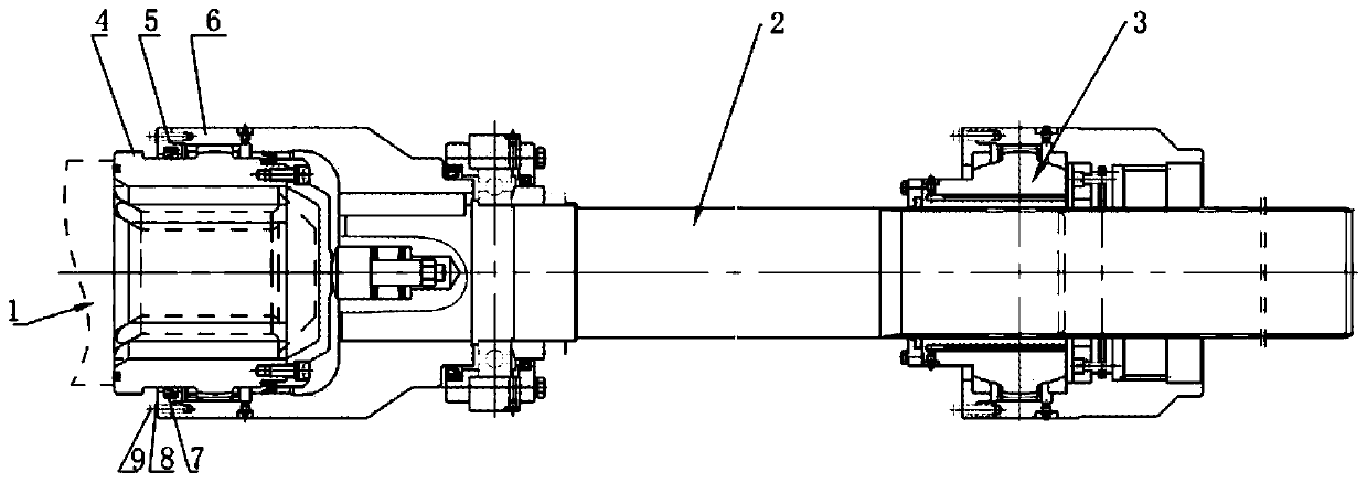
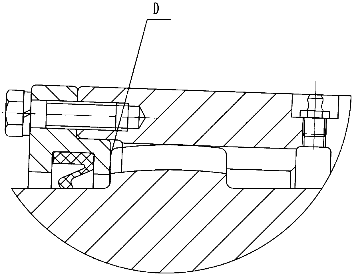
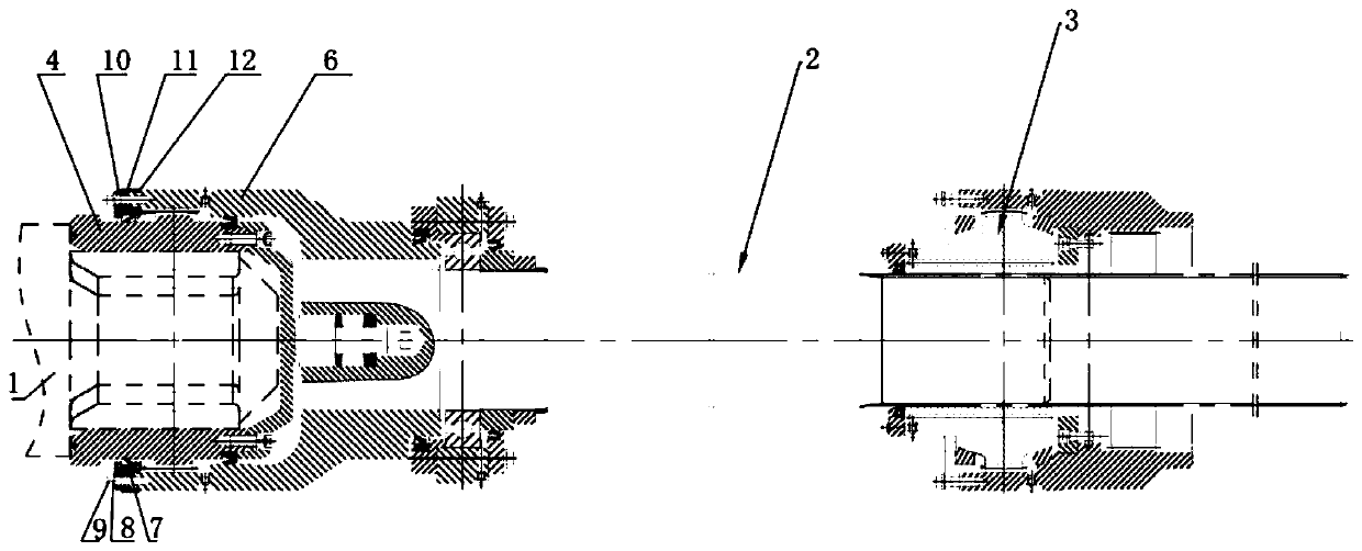
[0033] Such as image 3 As shown, the anti-loosening device of the coupling includes a tooth end assembly 3, a shaft assembly 2 and a roller end assembly, the shaft assembly 2 is placed between the roller end assembly and the tooth end assembly 3, and the roller end assembly includes the roller end external gear sleeve 4, The gland assembly and the roller end internal gear ring 6; the gland assembly is composed of the first gland 10 and the second gland 11 which are in contact with each other, and the inner ring of the gland assembly is assembled on the outer ring of the roller end external gear sleeve 4 , the gland assembly is fixedly connected to the end surface of the inner ring gear 6 at the roller end through fasteners. Such as image 3 As shown, the inner circle of one end of the above-mentioned second gland 11 cooperates with the outer circumference of the first gland 10, and the inner cir...


PUM


Abstract

The invention relates to a coupling preventing-loosing device which comprises a tooth end assembly, a shaft assembly and a roller end assembly, wherein the shaft assembly is arranged between the roller end assembly and the tooth end assembly; the roller end assembly comprises a roller end external tooth shaft sleeve, a gland assembly and a roller end internal gear ring; the gland assembly is composed of a first gland and a second gland propped against each other; the inner ring of the gland assembly is assembled on the outer ring of the roller end external tooth shaft sleeve; and the gland assembly is fixedly connected with the end face of the roller end internal gear ring through a fastener. The coupling preventing-loosing device is simple in structure and convenient to use; the traditional cover body structure is changed into a combined type gland formed by combining the first gland and the second gland, so that the axial force generated by the coupling to the gland during the mounting, detaching and using process of the coupling is transferred to the gland and the roller end internal gear ring, a fastening bolt is prevented from receiving larger axial force, and the labor efficiency is improved.

Description

technical field [0001] The invention relates to the field of mechanical transmission equipment, in particular to a shaft coupling anti-loosening device for mechanical structural parts with glands. Background technique [0002] With the advancement of my country's infrastructure construction, the market demand for bars, wires and other steel bars is increasing. Each bar and wire production line needs large-scale, efficient, continuous, and high-precision rolling equipment. Therefore, new requirements are proposed for the related spare parts industry challenge. In order to meet the requirements of on-site production of high-precision, high-quality bar, wire and steel bar products, continuous and efficient operation of mechanical transmission equipment is required. [0003] Such as figure 1 As shown, the structure of the existing rod and wire main drive coupling is as follows: the tooth end assembly 3 is installed on the output shaft of the reducer, the shaft assembly 2 is pla...

Claims


Application Information

Patent Timeline
Patent Type & Authority Applications(China)
IPC IPC(8): B21B35/14
CPCB21B35/14
Inventor 薛海义陈兴贵
Owner 唐陌传动机械(无锡)有限公司
Why Eureka
Try Eureka