Intramedullary nail sighting device

A technology for aimers and intramedullary nails, applied in the field of intramedullary nail aimers, can solve the problems of inconvenient operation and increased cost of medical equipment

Pending Publication Date: 2020-01-17
KANGHUI MEDICAL INNOVATION
View PDF0 Cites 0 Cited by
  • Summary
  • Abstract
  • Description
  • Claims
  • Application Information

AI Technical Summary

Problems solved by technology

This directly increases the cost of medical equipment in the hospital objectively, and brings inconvenience to the operation to a certain extent.

Method used


Image

  • Intramedullary nail sighting device
  • Intramedullary nail sighting device
  • Intramedullary nail sighting device

Examples


Embodiment Construction

[0019] The technical solutions of the present invention will be specifically described below in conjunction with the accompanying drawings, and the described implementations are part of the implementations of the present invention, not all of them. Based on the implementation manners in the present invention, all other implementation manners obtained by persons of ordinary skill in the art without making creative efforts belong to the scope of protection of the present invention.

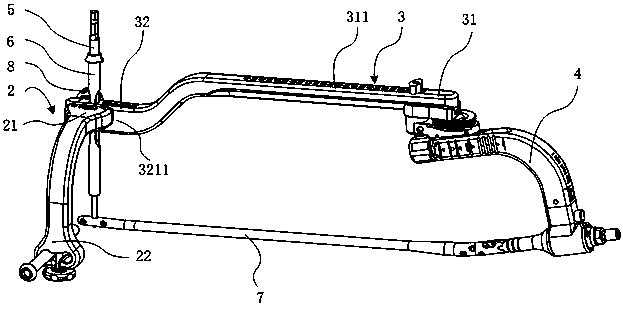
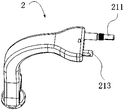
[0020] figure 1 It is a schematic structural view of an intramedullary nail aligner according to an embodiment of the present invention. The intramedullary nail aimer 1 includes a lateral bracket 2 , a gear bracket 3 , a handle 4 and at least one locking nut 8 . The lateral support 2 has a connecting end 21 and a free end 22 . The connecting end 21 of the lateral support 2 is connected to the distal end 32 of the gear support 3 through a connecting section 321 , and the connecting end 21 has a thr...


PUM


Abstract

The invention relates to an intramedullary nail sighting device, which comprises a handle, a lateral support, a position support and at least one locking nut. The lateral support can be connected to either side of the two sides of the position support so as to meet the surgical requirements for intramedullary nail implantation of affected limbs on the left side and right side. The intramedullary nail sighting device is more convenient to apply and helps reduce the cost of hospital surgical instruments.

Description

technical field [0001] The invention relates to the technical field of orthopedic medical instruments, in particular to an intramedullary nail aimer. Background technique [0002] The use of intramedullary nails to treat fractures is a commonly used internal fixation method for fractures, especially the preferred method for fractures of the femur, tibia, and humerus. Based on the structural characteristics of the intramedullary nail, it is a biological fixation (relatively stable), and the stress distribution is relatively uniform, which has little effect on the fracture end, and its elasticity is beneficial to fracture healing. [0003] In clinical practice, intramedullary nail aiming and fixation is often assisted by an intramedullary nail aimer. In this process, the intramedullary nail, handle, proximal aiming device, gear support, distal aiming device, and lateral support are assembled first, and then the distal positioning platform of the intramedullary nail is adjuste...

Claims


Application Information

Patent Timeline
Patent Type & Authority Applications(China)
IPC IPC(8): A61B17/72A61B17/90
CPCA61B17/7233A61B17/88A61B17/90
Inventor 秦宗俊李元勋杨兆权裴磊刘博柯林华
Owner KANGHUI MEDICAL INNOVATION
Why Eureka
Try Eureka