Sapling lifting device for garden construction
A technology for saplings and gardens, applied in the field of sapling raising devices for garden construction, can solve problems such as low work efficiency, inconvenience, and spread around, and achieve the effects of convenient placement, ensuring passability, and ensuring firmness
- Summary
- Abstract
- Description
- Claims
- Application Information
AI Technical Summary
Problems solved by technology
Method used
Image
Examples
Embodiment 1
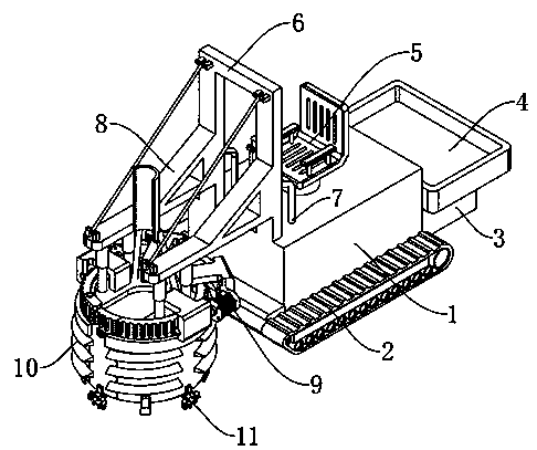
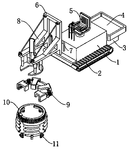
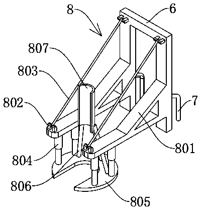
[0027] see Figure 1-3 , a sapling raising device for garden construction, comprising a fuselage main body 1 and a traveling crawler belt 2, the traveling crawler belt 2 is fixedly installed on both sides of the fuselage main body 1, a power unit is installed inside the fuselage main body 1, and the power unit is connected with the traveling crawler belt. The track 2 is matched; the rear end of the fuselage main body 1 is fixedly connected with a counterweight 3, the upper surface of the counterweight 3 is fixedly connected with a load box 4, and the upper surface of the fuselage main body 1 is fixedly installed with a driver's seat 5, A control mechanism is arranged around the driver's seat 5, and the front end of the fuselage main body 1 is fixedly connected with a fixed frame 6, and a reinforcing frame 7 is fixedly connected between the fixed frame 6 and the fuselage main body 1, and the fixed frame 6 is also connected with a connection fixing mechanism. 8. A drive mechanis...
Embodiment 2
[0031] see Figure 4-5 , based on Embodiment 1, the difference is that;
[0032] The drive mechanism 9 includes a first connecting block 901 and a second connecting block 905, the first connecting block 901 is fixedly connected to the connecting plate 805, and the first connecting block 901 is also fixedly connected with an arc-shaped fixing plate 902, the arc-shaped fixing plate The two ends of 902 are fixedly connected with servo motor 903, the output shaft of servo motor 903 is fixedly connected with worm screw 904, the second connecting block 905 is also fixedly connected on the connecting plate 805, and the worm screw 904 is connected with the second connecting block 905 in rotation.
[0033] The rotary planer soil raising device 10 includes an installation cover 1001, the outer wall surface of the installation cover 1001 is fixedly connected with an auger leaf 1002, and the inner wall top of the installation cover 1001 is fixedly connected with a limit ring body 1003, an...
Embodiment 3
[0037] refer to Image 6 ; Based on Embodiment 1 or 2, the difference is that;
[0038] The auxiliary digging mechanism 11 includes an inner gear ring 1101 and a connecting rod 1102, the inner gear ring 1101 is fixedly connected to the first connecting block 901 and the second connecting block 905, and the connecting rod 1102 is rotatably connected to the installation cover 1001 and the movable cover body 1006 Inside the side wall of the connecting rod 1102, the top end of the connecting rod 1102 is fixedly connected with a gear 1103, the gear 1103 is meshed with the inner gear ring 1101, and the bottom end of the connecting rod 1102 is fixedly connected with the first bevel gear 1104, and the first bevel gear 1104 is connected with the second bevel gear. The gear 1105 is obliquely engaged and connected, and the second bevel gear 1105 is also rotationally connected with the connecting ear 1106. The connecting ear 1106 is fixedly connected to the bottom end of the installation ...
PUM
 Abstract
Description
Claims
Application Information
 - R&D
- Intellectual Property
- Life Sciences
- Materials
- Tech Scout
- Unparalleled Data Quality
- Higher Quality Content
- 60% Fewer Hallucinations
Browse by: Latest US Patents, China's latest patents, Technical Efficacy Thesaurus, Application Domain, Technology Topic, Popular Technical Reports.
© 2025 PatSnap. All rights reserved.Legal|Privacy policy|Modern Slavery Act Transparency Statement|Sitemap|About US| Contact US: help@patsnap.com


