A wireless network transmitting terminal equipped with an optical fiber detection device for communication engineering

A technology of optical fiber detection and wireless network, applied in the coupling of optical waveguide, fiber mechanical structure, electrical components, etc., can solve the problems of troublesome maintenance of staff, paralysis of telecommunication system, low degree of modularization, etc.

Active Publication Date: 2021-04-06
李昊鸣
View PDF4 Cites 0 Cited by
  • Summary
  • Abstract
  • Description
  • Claims
  • Application Information

AI Technical Summary

Problems solved by technology

[0004] The modularization of the existing telecommunication system is in the initial stage, and the degree of modularization of each part is low. Usually, if a certain telecommunication terminal fails in a certain area, the telecommunication system in this area will be in a state of paralysis for a long time, and the maintenance of the staff is relatively difficult. Trouble, seriously affecting user experience

Method used


Image

  • A wireless network transmitting terminal equipped with an optical fiber detection device for communication engineering
  • A wireless network transmitting terminal equipped with an optical fiber detection device for communication engineering
  • A wireless network transmitting terminal equipped with an optical fiber detection device for communication engineering

Examples


Embodiment 1

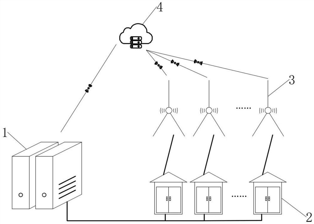
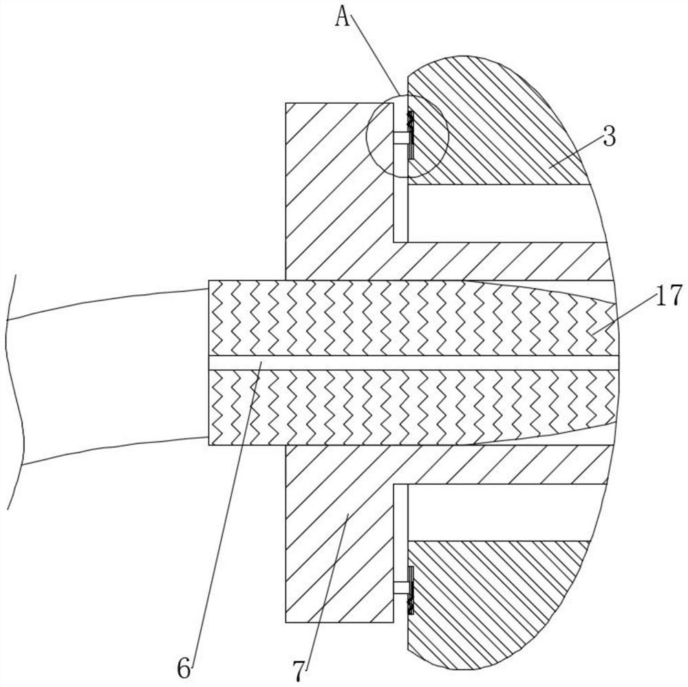
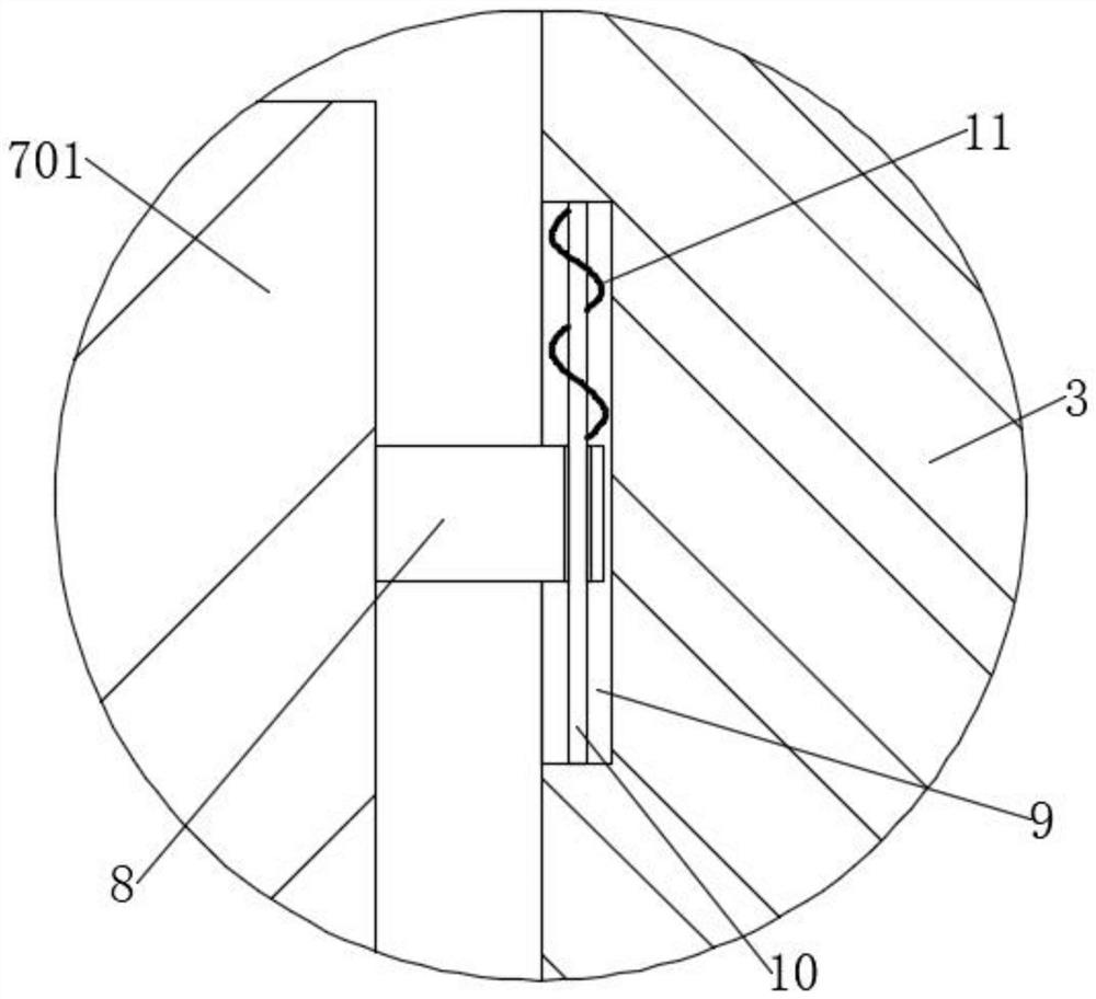
[0034] see Figure 2-3 , including a wireless signal terminal 3, the wireless signal terminal 3 is connected to a wired signal terminal 2, the wired signal terminal 2 is connected to a signal transmitting terminal 1, the wireless signal terminal 3 is connected to a cloud storage device 4, and the cloud storage device 4 is connected to the signal transmitting terminal 1 For signal connection, a jack is drilled on the wireless signal terminal 3, and a pair of clips 7 are inserted into the jack, and the two clips 7 both include a limiting half-ring 701 and a collar 702, and the limiting half-ring 701 is located outside the jack , the collar 702 is plugged into the jack, and a pair of chute 9 is excavated on the wireless signal terminal 3, and a sliding rod 10 is fixedly connected between the side walls of the chute 9, and two stop rings 701 are respectively fixedly connected with The limit slider 8 matched with the chute 9, and the two slide bars 10 pass through the limit slider ...


PUM


Abstract

The invention discloses a wireless network transmitting terminal equipped with an optical fiber detection device for communication engineering, which belongs to the field of wireless transmitting terminals, and a wireless network transmitting terminal equipped with an optical fiber detection device for communication engineering. The modularization of the device forms a division of labor and cooperation similar to that of social social animals in nature, and manages each terminal and device separately, so that each terminal and module has an independent role and is maintained separately, reducing the damage of a single module to the entire communication Influenced by engineering, in the process of maintaining a single module, the staff can clearly observe the scattered optical signals after the optical fiber is bent through the kaleidoscope lens device, which is convenient for the staff to perform maintenance and inspection. When the optical fiber line is inspected and maintained , the fault point can be quickly located through the change of the positional relationship between the protective skin and the cooling sticker.

Description

technical field [0001] The invention relates to the field of wireless transmitting terminals, and more specifically relates to a wireless network transmitting terminal equipped with an optical fiber detection device for communication engineering. Background technique [0002] The tiny optical fiber is encapsulated in a plastic sheath so that it can be bent without breaking. Usually, the transmitting device at one end of the fiber uses a light-emitting diode or a laser to transmit light pulses to the fiber, and the receiving device at the other end of the fiber uses a photosensitive sensor. The component detects the pulse. The technology used by the optical fiber is total internal reflection, which means that the light is emitted from an optically dense medium (that is, the light has a large refractive index in this medium) to an optically sparse medium (that is, the light has a small refractive index in this medium) At the interface of the optical fiber, all of them are refl...

Claims


Application Information

Patent Timeline
Patent Type & Authority Patents(China)
IPC IPC(8): H04B10/079G02B6/44G02B6/38
CPCG02B6/38G02B6/44H04B10/0791H04B10/0795
Inventor 李昊鸣
Owner 李昊鸣
Why Eureka
Try Eureka