
Planar reflecting array antenna and formation method thereof

A reflection array antenna and planar reflection array technology, applied in the directions of antennas, antenna arrays, radiating element structures, etc., can solve problems such as limited practical value and complex bias loading circuits.

Inactive Publication Date: 2020-01-14
UNIV OF ELECTRONICS SCI & TECH OF CHINA
View PDF4 Cites 5 Cited by
  • Summary
  • Abstract
  • Description
  • Claims
  • Application Information

AI Technical Summary

Problems solved by technology

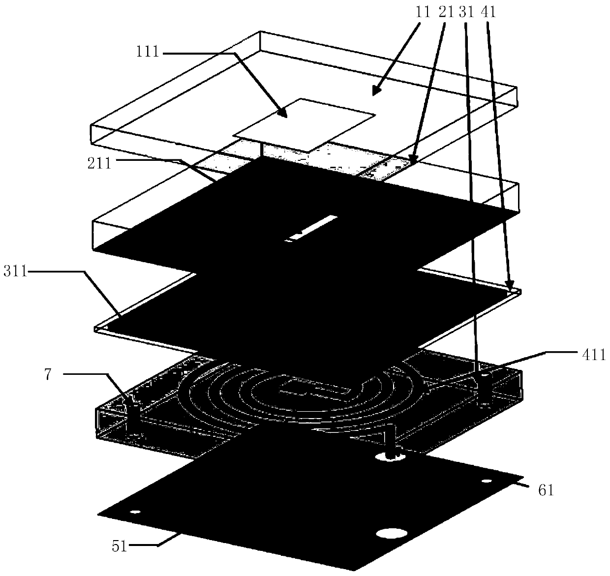
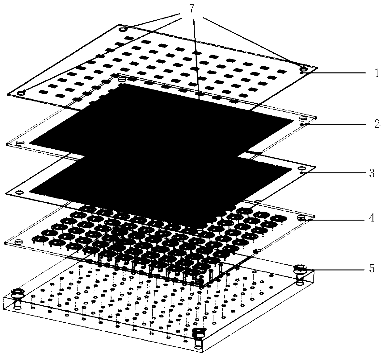
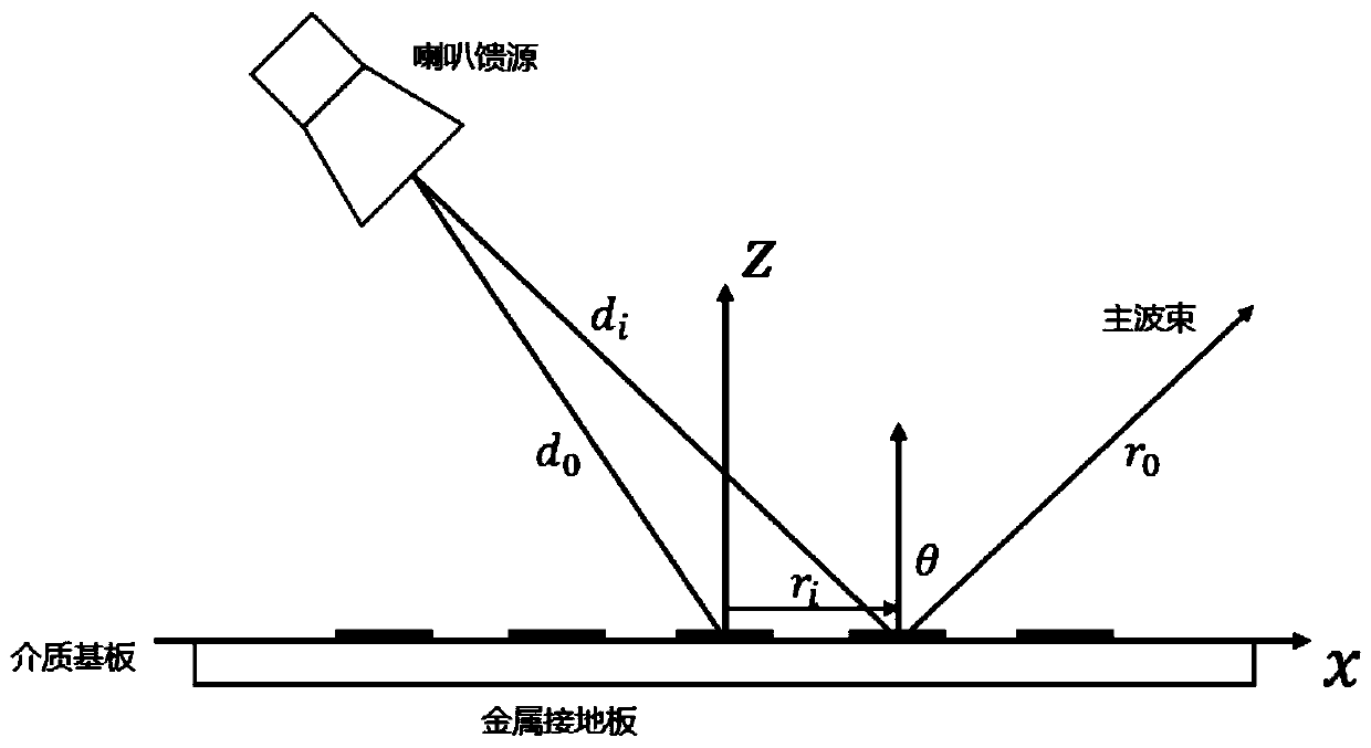
[0005] The purpose of the present invention is to provide a planar reflectarray antenna and its forming method to solve the problems in the related art that the reflectarray antenna can only realize one-dimensional direction scanning, and the bias loading circuit is too complicated and the practical value is limited

Method used


Image

  • Planar reflecting array antenna and formation method thereof
  • Planar reflecting array antenna and formation method thereof
  • Planar reflecting array antenna and formation method thereof

Examples


Embodiment Construction

[0031] The specific implementation manner of the present invention will be described in more detail below with reference to schematic diagrams. Advantages and features of the present invention will be apparent from the following description and claims. It should be noted that all the drawings are in a very simplified form and use imprecise scales, and are only used to facilitate and clearly assist the purpose of illustrating the embodiments of the present invention.

[0032] As mentioned in related technologies, existing reflectarray antennas designed based on liquid crystal materials can only realize one-dimensional direction scanning, but have not been able to realize two-dimensional scanning of beams. At the same time, the bias loading circuit is too complicated and has limited practical value.

[0033] Therefore, in the technical field of antennas, in order to solve the above problems, the present invention provides a planar reflectarray antenna.

[0034] A liquid crystal...


PUM

PropertyMeasurementUnit
thicknessaaaaaaaaaa

Abstract

The invention provides a planar reflecting array antenna and a formation method thereof. Compared with the existing antenna beam scanning technical scheme, the liquid crystal-based N x N electricallycontrolled scanning planar reflecting array antenna and the corresponding bias loading module can meet the requirements of independent and controllable phase of the reflecting unit, two-dimensional scanning of the antenna beam, low response time delay and the like. Meanwhile, the design using liquid crystal materials makes the design of the scheme extensible in higher frequency bands so as to provide a design basis for the miniaturization of antennas and improvethe application value and range of such reflecting array antennas.

Description

technical field [0001] The invention relates to the technical field of antennas, in particular to a planar reflectarray antenna and a forming method thereof. Background technique [0002] With the development of electronic information technology, satellite communication, radar detection, electronic countermeasures and other systems have increasing demands for high performance, miniaturization and light weight of communication equipment. As a key link of the wireless communication system, the antenna system has a restrictive influence on the performance, cost, and quality of the overall communication system. Therefore, the development of new high-performance antennas has become inevitable. Today's communication systems require new antennas with high gain, wide frequency band, miniaturization, light weight and beam scanning functions, which can meet the requirements of anti-jamming, positioning tracking, long-distance communication, etc. The new antennas have broad application...

Claims


Application Information

Patent Timeline
Patent Type & Authority Applications(China)
IPC IPC(8): H01Q1/36H01Q1/38H01Q1/50H01Q19/10H01Q21/00
CPCH01Q1/36H01Q1/38H01Q1/50H01Q19/10H01Q21/00
Inventor 蒋迪白天明李潇雨李善慈
Owner UNIV OF ELECTRONICS SCI & TECH OF CHINA
Learn More