
Horizon automatic interpretation method based on minimum seismic waveform unit classification

A seismic waveform and automatic interpretation technology, applied in the field of exploration geophysics, can solve problems such as low signal-to-noise ratio of seismic data, limited reliability of interpretation results, difficulty in meeting algorithm requirements, etc., to improve reliability and accuracy, reduce optimization difficulty, The effect of improving reliability

Active Publication Date: 2020-01-14
CHINA PETROLEUM & CHEM CORP +1
View PDF7 Cites 1 Cited by
  • Summary
  • Abstract
  • Description
  • Claims
  • Application Information

AI Technical Summary

Problems solved by technology

This method works well in areas with relatively simple structures, but when the structure is complex, it is difficult to guarantee the accuracy and reliability of horizons; the third type is the automatic tracking technology based on artificial neural networks, and Alberts (1999) and other applications This technology has achieved good results in horizon tracking, but it mainly uses a shallow neural network, and the reliability of the interpretation results is severely restricted by the number of training samples, and it is often difficult to meet the algorithm requirements in practical applications; the fourth category is The automatic horizon tracking method based on seismic attribute analysis, Emanuele (2015, 2016) used seismic phase attributes to pick horizons, but when the signal-to-noise ratio of seismic data is low, the stability of interpretation results cannot be guaranteed
In general, the above technology improves the automatic horizon tracking algorithm and has achieved certain application effects in practical applications, but it needs to be further improved in describing the mapping relationship between seismic data and horizons

Method used


Image

  • Horizon automatic interpretation method based on minimum seismic waveform unit classification
  • Horizon automatic interpretation method based on minimum seismic waveform unit classification
  • Horizon automatic interpretation method based on minimum seismic waveform unit classification

Examples


Embodiment Construction

[0031] The present invention will be further explained below in conjunction with specific embodiments. The detailed description and technical content of the present invention are described below with the accompanying drawings. However, the accompanying drawings are only provided for reference and description, and are not used to limit the present invention.

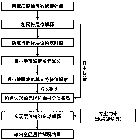
[0032] Such as figure 1 As shown, a flow chart of an embodiment of an automatic horizon interpretation method based on the minimum seismic waveform unit classification of the present invention, the specific steps of this embodiment are as follows:

[0033] (1) Perform continuity enhancement preprocessing on the seismic data of the target interval; perform continuity enhancement processing on the seismic data to obtain high-precision seismic data, highlighting the characteristics of the main stratigraphic framework and the fine stratigraphic framework.

[0034] (2) Coarse-grid horizon interpretation of the target horizon; ...


PUM


Abstract

The invention provides ahorizon automatic interpretation method based on minimum seismic waveform unit classification. The horizon automatic interpretation method includes the steps that 1, seismic data of a target interval are subjected to continuous enhancement pretreatment; 2, coarse-mesh horizon interpretation is carried out on target horizon; 3, a preliminary interpretation result obtained inthe step 2 is used as a control point of horizon time, and top and bottom time windows containing a plurality of complete seismic waveforms are obtained by shifting upwards and downwards; 4, seismicdata in the time windows are divided into minimum waveform units; 5, characteristic values of the minimum seismic waveform units are extracted; 6, a minimum seismic waveform unit classification modelof a random forest is constructed; and 7, a horizon automatic interpretation result of the whole area is optimized. According to the horizon automatic interpretation method, the difficulty of optimizing a horizon automatic recognition algorithm is lowered, meanwhile professional constraints are imposed, the reliability of the horizon automatic interpretation result is effectively improved, and good application prospects are achieved.

Description

technical field [0001] The invention relates to the field of exploration geophysics, and in particular provides an automatic layer interpretation method based on the classification of minimum seismic waveform units. Background technique [0002] In exploration and development, seismic horizon interpretation is the basis of oil and gas exploration, and its reliability directly affects the rationality of subsequent reservoir prediction and oil and gas reservoir evaluation results. In general, horizon interpretation is basically based on manual or single-section automatic tracking. Due to the limited field of view, it is often difficult to obtain satisfactory interpretation results in a short period of time, which greatly restricts the advancement of oilfield production. The traditional horizon interpolation algorithm is simple and has high execution efficiency, but it is prone to cross-axis phenomenon, and a large amount of manual intervention is still required in complex cons...

Claims


Application Information

Patent Timeline
Patent Type & Authority Applications(China)
IPC IPC(8): G01V1/28
CPCG01V1/28
Inventor 王树华于会臻谭绍泉林会喜景瑞林马承杰吴微李守济魏敏张建华
Owner CHINA PETROLEUM & CHEM CORP
Learn More