
Automatic slitting equipment for electronic digital detonator chip

An electronic digital detonator and chip technology, which is applied in metal processing and other directions, can solve the problems of no forming and reliable digital detonator chip automatic slitting equipment, inability to meet safety production and safety quota, and failure to achieve man-machine isolation, etc., to improve safety in production. The effect of management level and production efficiency, elimination of potential safety hazards, and simple structure

Pending Publication Date: 2020-01-14
长春汇维科技股份有限公司 +1
View PDF0 Cites 0 Cited by
  • Summary
  • Abstract
  • Description
  • Claims
  • Application Information

AI Technical Summary

Problems solved by technology

[0002] At present, domestic factories do not have reliable digital detonator chip automatic cutting equipment in the field of digital detonator production and assembly. Most manufacturers use manual assembly of chips in molds.
The main problems of this method are 1. There are many operators; 2. The labor intensity is high and the production efficiency is low; 3. The operators directly contact the detonator, and the isolation between man and machine is not realized. Capacity requirements

Method used


Image

  • Automatic slitting equipment for electronic digital detonator chip
  • Automatic slitting equipment for electronic digital detonator chip
  • Automatic slitting equipment for electronic digital detonator chip

Examples


Embodiment Construction

[0027] The present invention will be described in detail below in conjunction with the embodiments shown in the accompanying drawings.

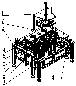
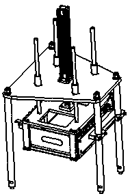
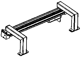
[0028] figure 1 As shown, the digital detonator chip automatic slitting equipment of the present invention includes making the upper mold and the lower mold enter the equipment to install the cut and separated chips and assemble them into a combined mold push-out equipment to enter the transmission equipment 1, and make the bottom mold enter the equipment. Bottom mold translation mechanism 2. Cut and separate the chips in the hopper and enter the corresponding bottom mold. Chip separation and switching mechanism 3. Separate the cut chips and enter the chip separation mechanism at the designated position 4. Make the upper and lower molds form a combined mold The mold clamping lifting mechanism 5, the push mold mechanism 6 that pushes the combined mold to the transmission equipment, the waste slideway mechanism that guides waste into the waste ...


PUM


Abstract

The invention discloses automatic slitting equipment for an electronic digital detonator chip, and relates to detonator production equipment. The automatic slitting equipment comprises a bottom die mechanism, a die clamping mechanism, a frame body mechanism, a material taking, slitting and die replacing mechanism, a waste collecting mechanism, a bottom die lifting mechanism, a bottom die center mechanism, a chip warehouse-out mechanism, a feeding mechanism and a die pushing device, wherein the bottom die mechanism is used for automatically conveying a chip die to a workbench and positioning the chip die, the die clamping mechanism is used for lifting an upper chip die body and assembling the upper die body and a lower die body together, the frame body mechanism is used for achieving the bearing supporting function and fixing the whole equipment, the material taking, slitting and die replacing mechanism is used for automatically replacing the chip, performing the slitting operation andmeanwhile replacing the die, the waste collecting mechanism is used for collecting slit waste, the bottom die lifting mechanism is used for lifting a bottom die to the workbench, the bottom die centermechanism is used for enabling a bottom die spring grasping hand to be manually unfolded, the chip warehouse-out mechanism is used for pushing out the cut chip in a storage bin, the feeding mechanismis used for bearing and lifting the chip, and the die pushing device is used for pushing out the assembled upper die body and lower die body. According to the automatic slitting equipment, a materialtaking, slitting and die replacing three-in-one chip separation scheme is adopted, a complex process is simplified, the volume of the equipment is reduced, meanwhile, the cost is saved, and in addition, the production efficiency is improved.

Description

technical field [0001] The invention relates to a detonator production device, in particular to an electronic digital detonator chip automatic cutting device. Background technique [0002] At present, domestic factories do not have reliable digital detonator chip automatic cutting equipment in the field of digital detonator production and assembly. Most manufacturers use manual assembly of chips in molds. The main problems of this method are 1. There are many operators; 2. The labor intensity is high and the production efficiency is low; 3. The operators directly contact the detonator, and the isolation between man and machine is not realized. Capacity requirements. Needs to be improved. Contents of the invention [0003] The object of the present invention is to provide a kind of automatic digital detonator chip slitting equipment, the chip of the present invention is automatically slit and discharged into the mould, improves the production efficiency, can fully realize...

Claims


Application Information

Patent Timeline
Patent Type & Authority Applications(China)
IPC IPC(8): B26F1/40B26F1/44B26D7/06B26D7/18
CPCB26F1/40B26F1/44B26D7/06B26D7/1827B26F2001/4463
Inventor 刘毅李新斌黄志斌谷峻峰王浩李兆歧邵志
Owner 长春汇维科技股份有限公司
Learn More