A Control Method of Active Clamp Flyback Converter

A flyback converter and control method technology, applied in control/regulation systems, DC power input conversion into DC power output, instruments, etc., can solve the problem of clamping capacitor energy not being released, etc., to achieve high light load efficiency, The effect of low no-load power consumption

Active Publication Date: 2020-09-15
MORNSUN GUANGZHOU SCI & TECH
View PDF2 Cites 0 Cited by
  • Summary
  • Abstract
  • Description
  • Claims
  • Application Information

AI Technical Summary

Problems solved by technology

However, in each switching cycle, the converter will charge the clamp capacitor through the body diode of the clamp switch tube. Since the clamp switch tube is not working, the energy on the clamp capacitor cannot be released.

Method used


Image

  • A Control Method of Active Clamp Flyback Converter
  • A Control Method of Active Clamp Flyback Converter
  • A Control Method of Active Clamp Flyback Converter

Examples


Embodiment Construction

[0024] In one embodiment, the active clamp flyback converter is used to regulate the input voltage and output a desired voltage, the active clamp flyback converter includes a main switch tube for controlling the current magnitude of the primary winding of the flyback transformer, and A clamp switch tube that clamps the node voltage on the primary side of the flyback transformer. The controller generates control signals for controlling the main switch and the clamp switch by detecting a feedback (FB) voltage.

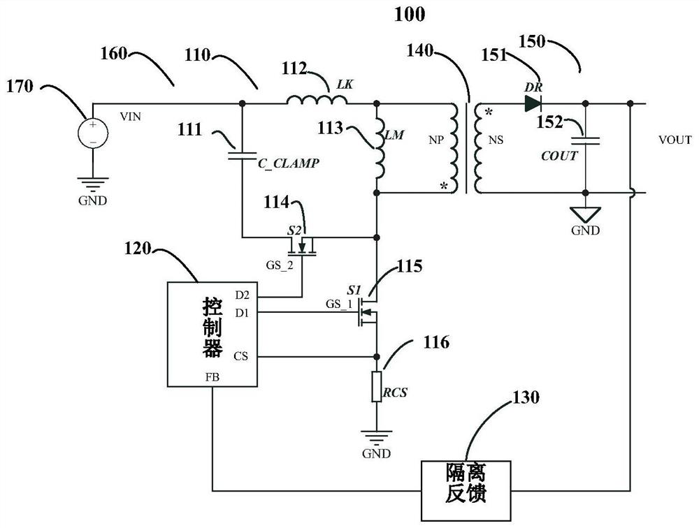
[0025] figure 1 An active clamp flyback power supply 100 according to some embodiments is presented in schematic form. Wherein 100 includes an active clamp flyback (ACF) converter 160 and a controller 120 for adjusting the input voltage of the voltage source 170 and outputting a desired output voltage V out .

[0026] The ACF converter 160 includes a primary side circuit 110 , a flyback transformer 140 , and a secondary side circuit 150 . Both the primary winding and...


PUM


Abstract

The invention discloses a control method of an active clamp flyback converter. In the flyback transformer, the main switch tube controls the current magnitude of the primary winding of the flyback transformer, and the clamp switch tube controls the primary side of the flyback transformer. The node voltage is clamped, and the controller generates a control signal for controlling the main switch tube and the clamp switch tube by detecting the feedback voltage; when the converter works at a light load, a fixed dead time passes after the main switch tube is turned off Immediately turn on the clamp switch tube, the converter charges the clamp capacitor through the clamp switch tube to recover leakage inductance energy, wherein the conduction time of the clamp switch tube is less than the leakage inductance and the output junction capacitance of the main switch tube and the clamp switch tube the resonance period. The present invention does not need to connect a large resistor in parallel to the clamp capacitor, thereby improving the light-load efficiency.

Description

technical field [0001] The invention relates to a flyback converter, in particular to a control method for an active clamp flyback converter. Background technique [0002] Flyback converters are widely used in small and medium power switching power supplies because of their low cost and simple topology. In the actual working process, due to the existence of the leakage inductance of the flyback converter, the energy of the primary side cannot be completely transferred to the secondary side, and the resonance between the leakage inductance energy left on the primary side and the junction capacitance of the MOS tube causes the drain of the main switch tube Generate high frequency voltage spikes. In order to reduce the voltage stress of the switch tube when making products, it is common practice to add suitable snubber circuits. Common snubber circuits include RCD snubber circuits, LCD snubber circuits and active clamp circuits. Among them, the active clamping circuit adds an...

Claims


Application Information

Patent Timeline
Patent Type & Authority Patents(China)
IPC IPC(8): H02M3/335
CPCH02M3/33569
Inventor 尹向阳王海洲袁源刘湘
Owner MORNSUN GUANGZHOU SCI & TECH
Why Eureka
Try Eureka