Crimping surface adaptive crimping machine

An adaptive, crimping machine technology, applied in the field of automation, can solve the problems of defective products, crimping failure, difficult process, etc., to achieve the effect of automatic and efficient replacement

Pending Publication Date: 2020-01-10
SHENZHEN XING GRAIN AUTOMATION CO LTD
View PDF0 Cites 3 Cited by
  • Summary
  • Abstract
  • Description
  • Claims
  • Application Information

AI Technical Summary

Problems solved by technology

[0002] The connector is a very common electronic component, which is often used to be inserted on the PCB board. The bottom of the connector is equipped with double-row side-by-side metal pins, and the metal pins are inserted into the correspondingly designed pin holes on the PCB board. , to achieve electrical conduction; the assembly of connectors is a production work with high precision requirements and difficult processes; at present, the following technical difficulties need to be overcome in the connector assembly process: 1. The crimping head is specially designed for the connector, and the connector is pressed into the pinhole of the PCB board through the crimping head. During the crimping process, since the crimping head and the connector pins are in surface contact, when the planes of the two are not parallel The position where the connector first contacts the pin is pressed deeper than the position where the second contact pin is. In this case, the pin kneeling is very likely to occur, resulting in crimping failure and defective products; 2. Different connectors require different crimping heads for crimping , in order to improve the versatility of the equipment, it is necessary to design a convenient clamping and replacement of the indenter and the indenter replacement mechanism

Method used


Image

  • Crimping surface adaptive crimping machine
  • Crimping surface adaptive crimping machine
  • Crimping surface adaptive crimping machine

Examples


Embodiment 1

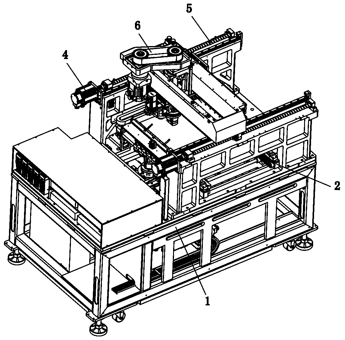
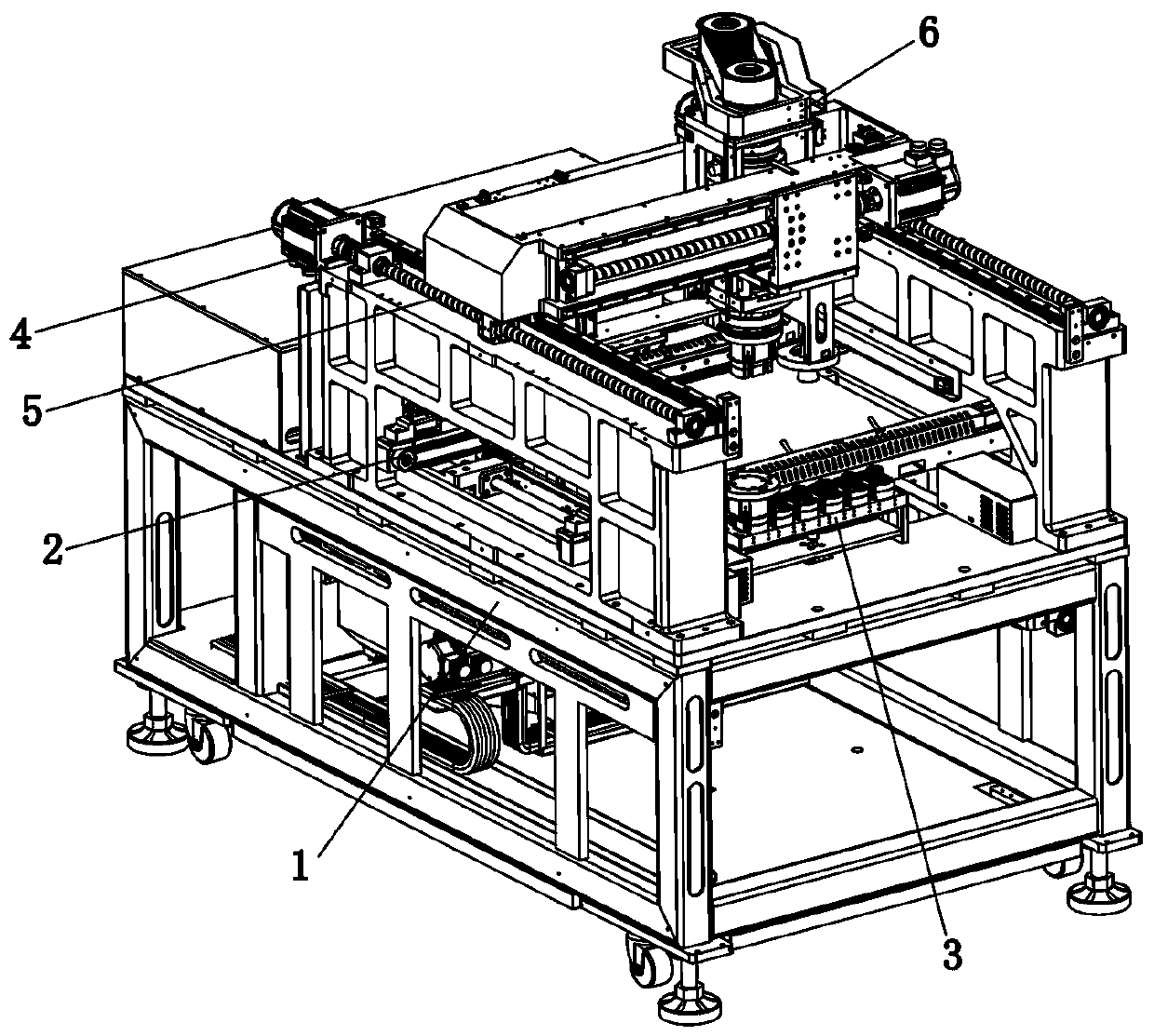
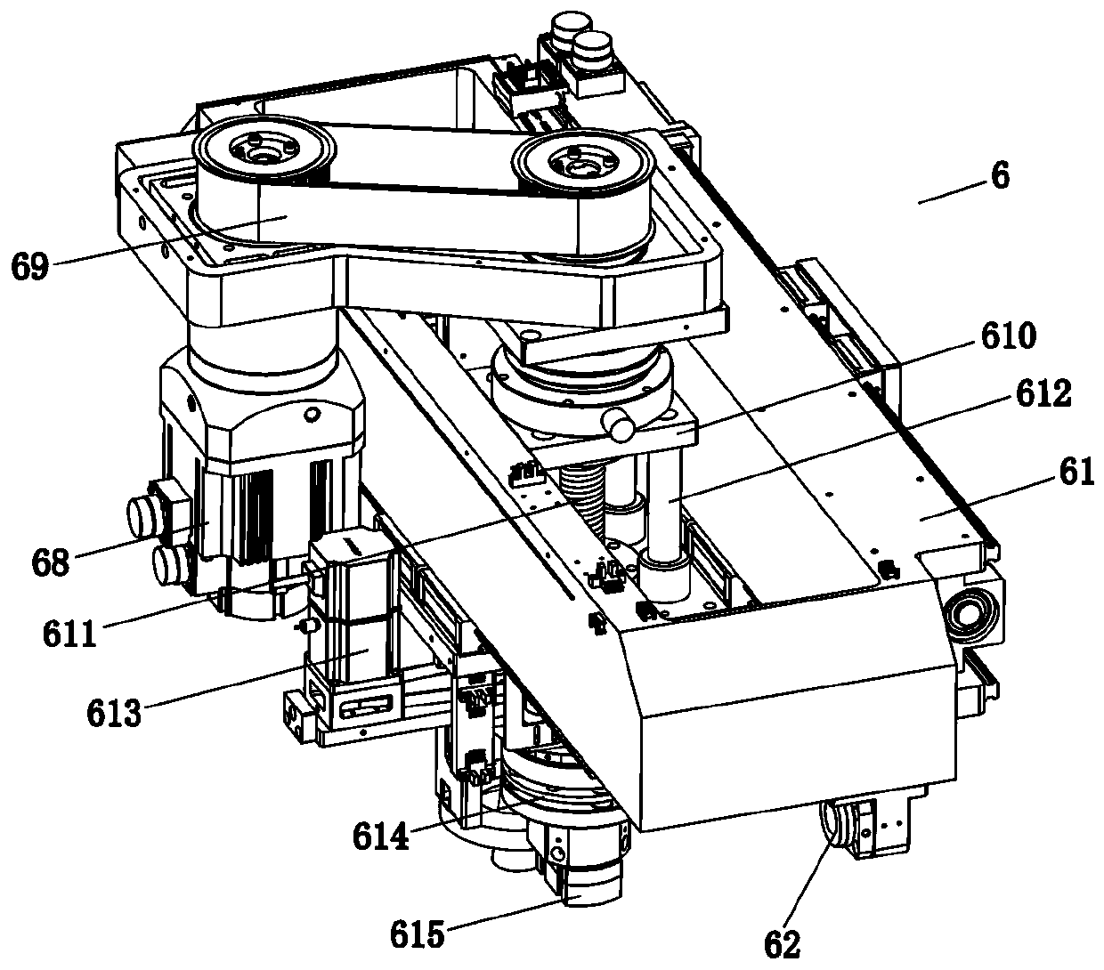
[0040] Embodiment 1: as Figure 1 to Figure 17 As shown, the technical solution adopted in Embodiment 1 of the present invention is as follows: a crimping surface self-adaptive crimping machine, comprising a frame 1 and a conveyor belt 2 arranged on the frame 1. The PCB board, and straightly transport the PCB board forward, also includes a first drive assembly, a crimping mechanism 6 and a replacement mechanism 3, wherein the above-mentioned first drive assembly straddles the transmission belt 2 in a direction perpendicular to the transmission belt 2 The above crimping mechanism 6 is connected to the first drive assembly, and is driven by the first drive assembly to move linearly; the crimping mechanism 6 includes a driving part, a connecting part 614 and a crimping part 615, and the driving part is connected to the first driving assembly On the output end of the drive assembly, the connection part 614 is connected to the output end of the drive assembly, and the drive assembl...

Embodiment 2

[0052] Embodiment 2: as Figure 18 to Figure 20 As shown, compared with Embodiment 1, Embodiment 2 of the present invention simplifies the structure of the crimping mechanism, omits the first transmission belt in Embodiment 1, and the first motor directly drives the rotation of the third screw rod to realize the lifting control function. ; Compared with Embodiment 1, this kind of structural design is simpler, and the production cost of the equipment is reduced.


PUM


Abstract

The invention discloses a crimping surface adaptive crimping machine which comprises a first driving assembly, a crimping mechanism and a replacement mechanism. The first driving assembly spans abovea transmission belt along a direction perpendicular to the transmission belt. The crimping mechanism is connected on the first driving assembly. The crimping mechanism comprises a driving part, a connecting part and a crimping part. The driving part is connected on the output end of the first driving assembly. The connecting part is connected on the output end of the driving assembly. The crimpingpart is arranged below the connecting part and is arranged at intervals with the connecting part, and the lower part of the crimping part is detachably connected with a crimping joint. An adaptive sphere and a flexible connecting plate are arranged in a gap space between the crimping part and the connecting part, and the adaptive sphere is rotatably connected in the gap between the flexible connecting plate and the connecting part or the gap between the flexible connecting plate and the crimping part. The replacement mechanism is arranged at the side of the transmission belt. The adaptive parallel bonding of the crimping surface and the automatic disassembling and assembling of the crimping joint can be realized.

Description

technical field [0001] The invention relates to the field of automation, in particular to a crimping surface self-adaptive crimping machine. Background technique [0002] The connector is a very common electronic component, which is often used to be inserted on the PCB board. The bottom of the connector is equipped with double-row side-by-side metal pins, and the metal pins are inserted into the correspondingly designed pin holes on the PCB board. , to achieve electrical conduction; the assembly of connectors is a production work with high precision requirements and difficult processes; at present, the following technical difficulties need to be overcome in the connector assembly process: 1. The crimping head is specially designed for the connector, and the connector is pressed into the pinhole of the PCB board through the crimping head. During the crimping process, since the crimping head and the connector pins are in surface contact, when the planes of the two are not para...

Claims


Application Information

Patent Timeline
Patent Type & Authority Applications(China)
IPC IPC(8): H01R43/20
CPCH01R43/20
Inventor 宾兴李明星李太松
Owner SHENZHEN XING GRAIN AUTOMATION CO LTD
Why Eureka
Try Eureka