
Luminous backlight source of single-ring sag type curved surface cathode three-back-arc-layer gating structure

A curved cathode and backlight technology, applied in the manufacture of cold cathode tubes, solid cathodes, and cold cathodes, can solve the problems of carbon nanotube cathodes losing control functions, losing essential functions, and not being able to emit electrons from carbon nanotube cathodes.

Inactive Publication Date: 2020-01-10
JINLING INST OF TECH
View PDF3 Cites 1 Cited by
  • Summary
  • Abstract
  • Description
  • Claims
  • Application Information

AI Technical Summary

Problems solved by technology

[0003] However, there are still some technical difficulties to be solved in the light-emitting backlight with three-pole structure
For example, on the one hand, the control performance of the gate voltage on the electron emission of the carbon nanotube layer is relatively poor
A smaller gate voltage cannot make the carbon nanotube cathode emit electrons at all, and a larger gate voltage can easily make the electron emission of the carbon nanotube cathode easy to get out of control; at the same time, the electron emission of the carbon nanotube cathode The quantity does not change strictly with the change of the gate voltage, these are the performance of the gate voltage losing the good control function of the carbon nanotube cathode
Second, the electron emission efficiency of the carbon nanotube cathode is relatively low
Without a sufficient number of carbon nanotubes to emit electrons at the same time, it is impossible to form a large cathode current for a luminescent backlight
However, in the carbon nanotube cathode, some carbon nanotubes do not emit electrons at all, and lose their essential function as a cathode; although some carbon nanotubes can emit electrons, the number of emitted electrons is too small to be sufficient. It acts as a source of electrons

Method used


Image

  • Luminous backlight source of single-ring sag type curved surface cathode three-back-arc-layer gating structure
  • Luminous backlight source of single-ring sag type curved surface cathode three-back-arc-layer gating structure
  • Luminous backlight source of single-ring sag type curved surface cathode three-back-arc-layer gating structure

Examples


Embodiment Construction

[0049] The present invention will be further described below in conjunction with the accompanying drawings and embodiments, but the present invention is not limited to this embodiment.

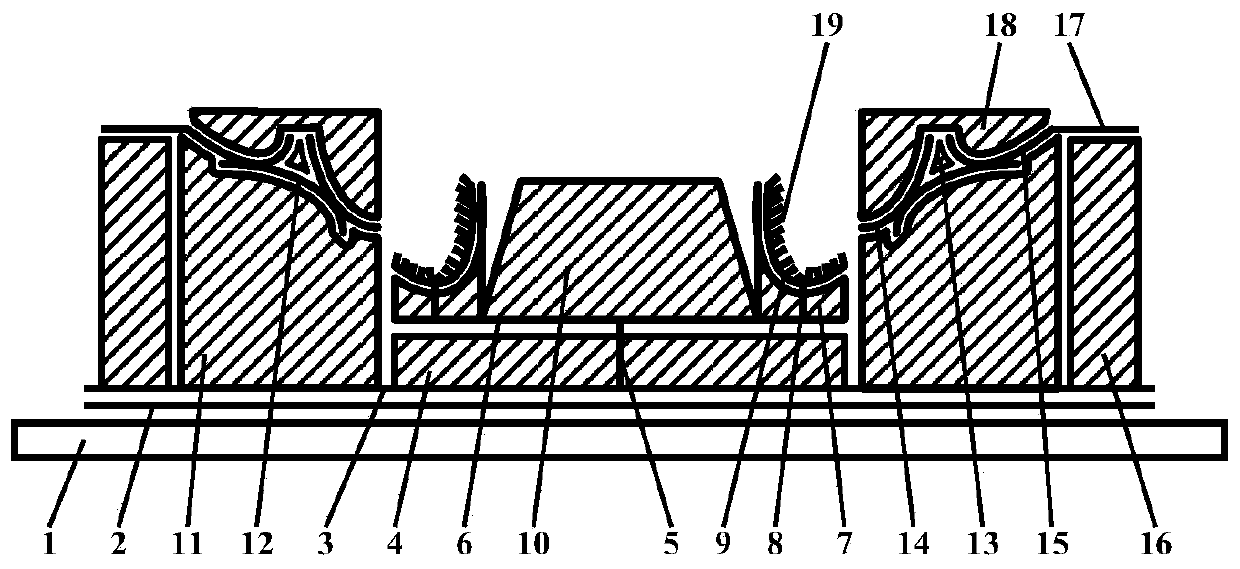
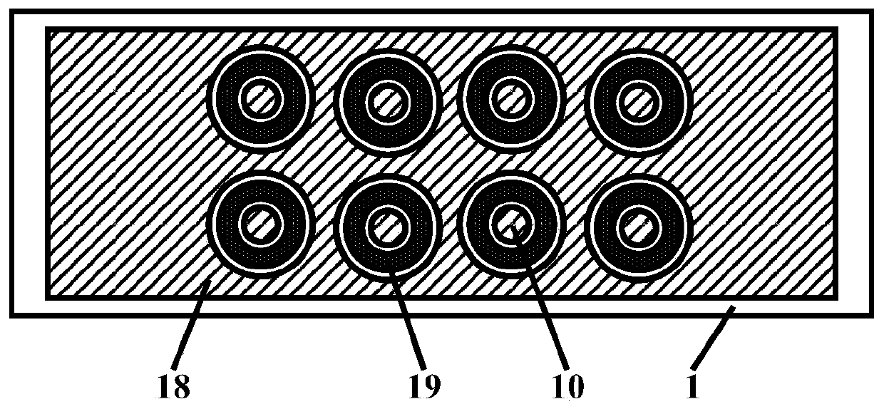
[0050] The light-emitting backlight of the single-ring groove-shaped curved surface cathode with three back-arc layer gating structures in this embodiment is as follows: figure 1 , figure 2 with image 3 As shown, it includes a vacuum enclosure and a getter 24 accessory components located in the vacuum enclosure; the vacuum enclosure is composed of a front transparent hard glass plate 20, a rear transparent hard glass plate 1 and a glass narrow frame strip 25; the front transparent The hard glass plate has an anode bottom film conductive layer 21, an anode bend connecting silver layer 22 and a thin light-emitting layer 23, the anode bottom film conduction layer is connected to the anode bend connection silver layer, and the thin light-emitting layer It is made on the conductive layer of the...


PUM


Abstract

The invention discloses a luminous backlight source of a single-ring sag type curved surface cathode three-back-arc-layer gating structure. The luminous backlight source comprises a vacuum sealing body and a getter accessory component located in the vacuum sealing body. The vacuum sealing body is composed of a front transparent hard glass plate, a rear transparent hard glass plate and a narrow glass frame strip. An anode bottom film power transmission layer, an anode bent silver-connected electric layer and a thin light-emitting layer are arranged on the front transparent hard glass plate, theanode bottom film power transmission layer is connected with the anode bent silver-connected electric layer, and the thin light-emitting layer is manufactured on the anode bottom film power transmission layer. The single-ring sag type curved surface cathode three-back-arc-layer gating structure is arranged on the rear transparent hard glass plate. The luminous backlight source has advantages thata manufacturing process is reliable and luminous gray scale adjustable performance of the luminous backlight source is good.

Description

technical field [0001] The present invention belongs to the fields of plane display technology, vacuum science and technology, semiconductor science and technology, microelectronics science and technology, nanometer science and technology, integrated circuit science and technology, and optoelectronic science and technology. It relates to the production of planar light-emitting backlight, specifically to the production of planar light-emitting backlight of carbon nanotube cathode, in particular to a kind of light-emitting backlight with single-ring groove-shaped curved surface cathode with three back-arc layer gating structure and its production craft. Background technique [0002] Carbon nanotubes have a small tip curvature radius, good electrical conductivity and excellent mechanical strength. They are also a suitable cathode material and have been widely used in various vacuum components. For the production of carbon nanotube cathodes, many researchers have conducted rese...

Claims


Application Information

Patent Timeline
Patent Type & Authority Applications(China)
IPC IPC(8): H01J17/06H01J17/04H01J17/12H01J17/38H01J17/48H01J9/02H01J9/20
CPCH01J9/02H01J9/025H01J9/20H01J17/04H01J17/066H01J17/12H01J17/38H01J17/48
Inventor 李玉魁
Owner JINLING INST OF TECH
Learn More