Eureka AIR delivers breakthrough ideas for toughest innovation challenges, trusted by R&D personnel around the world.

An anti-water hammer stop valve

A shut-off valve and water hammer technology, applied in the field of shut-off valves, can solve problems such as complex structure, many parts, damage to valve pipelines, etc.

Active Publication Date: 2021-05-11
GUANGZHOU UNIVERSITY
View PDF7 Cites 3 Cited by
  • Summary
  • Abstract
  • Description
  • Claims
  • Application Information

AI Technical Summary

Problems solved by technology

[0004] 1. Complex structure, many parts, large volume and high cost;
[0005] 2. There is no anti-water hammer device. When the downstream water supply device has a large amount of water and closes it quickly, the shock wave generated by the liquid will propagate upstream, causing damage to the valve and even the pipeline.

Method used


Image

  • An anti-water hammer stop valve
  • An anti-water hammer stop valve
  • An anti-water hammer stop valve

Examples


Embodiment 1

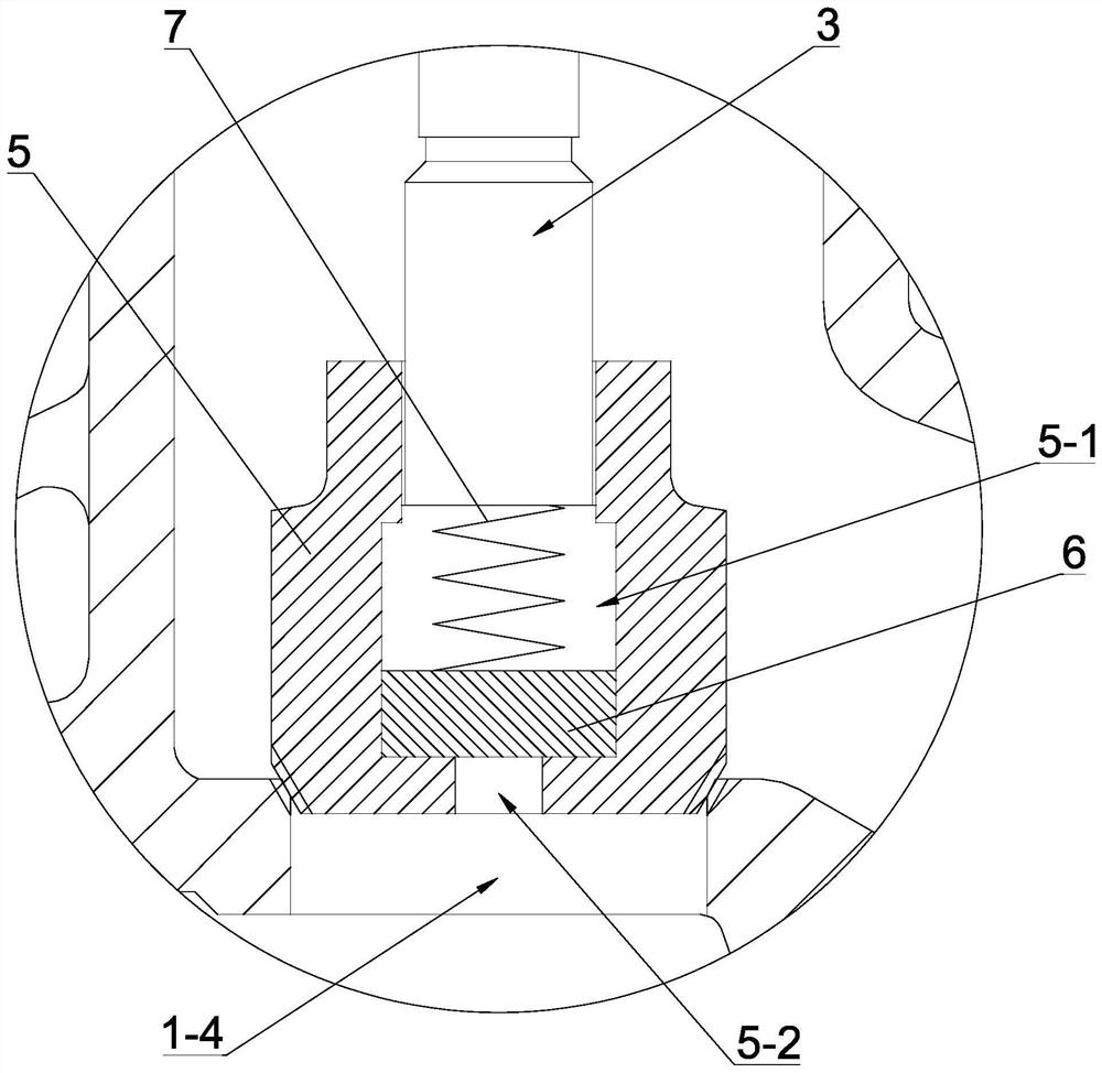
[0036] see Figure 1-Figure 2 , an anti-water hammer stop valve, comprising a valve body 1, the two ends of the valve body 1 are respectively provided with a water inlet 1-1 and a water outlet 1-2, and the water inlet 1-1 and the water outlet 1- 2 communicate through the inner cavity 1-3 of the valve body, and a communication port for connecting the water inlet 1-1 with the inner cavity 1-3 of the valve body is provided between the water inlet 1-1 and the inner cavity 1-3 of the valve body 1-4, the upper end of the valve body 1 is provided with a valve cover 2, the valve cover 2 is provided with a valve stem 3, the upper end of the valve stem 3 is connected with the hand wheel 4, and the lower end passes through the valve cover 2 and extends To the inner cavity 1-3 of the valve body, the lower end of the valve stem 3 is provided with a valve disc 5 fixedly connected with the valve stem 3 and used to close and open the communication port 1-4. It is characterized in that the val...

Embodiment 2

[0053] see image 3 , in this embodiment, the anti-water hammer sliding member 6 is arranged in the sliding hole 5-1 and is slidably fitted with the sliding hole 5-1, and the compression spring 7 is arranged in the sliding hole 5-1 1 and located between the anti-water hammer sliding piece 6 and the valve stem 3, one end of the compression spring 7 acts on the bottom of the valve stem 3, and the other end acts on the bottom of the anti-water hammer sliding piece 6 top. The design of the above structure is simple. When the valve is opened or closed, the water hammer generated when the valve is closed or opened can be buffered by the action of the anti-water hammer sliding part 6 and the compression spring 7, effectively reducing the water pressure of the valve and the pipeline. , Play the role of protecting valves and pipelines.


PUM


Abstract

The invention discloses an anti-water hammer stop valve, which comprises a valve body. The two ends of the valve body are respectively provided with a water inlet and a water outlet. The water inlet and the water outlet are connected through the inner cavity of the valve body. There is a communication port between the inner cavity of the valve body, a valve cover is provided at the upper end of the valve body, a valve stem is provided on the valve cover, the upper end of the valve stem is connected with the hand wheel, and the lower end passes through the valve cover and extends To the inner cavity of the valve, a valve disc is provided at the lower end of the valve stem, and an anti-water hammer device is provided between the valve body and the valve disc, wherein the valve disc is a hollow structure, and its inner cavity is composed of a sliding hole and an inlet Water hole structure; the anti-water hammer device includes an anti-water hammer sliding piece and a compression spring, the anti-water hammer sliding piece is arranged in the sliding hole, one end of the compression spring acts on the bottom of the valve stem, and the other end acts on the bottom of the valve stem. On the top of the anti-water hammer sliding part; the compression spring has a pre-compression amount, and always keeps the anti-water hammer sliding part close to the water inlet hole. The globe valve has the function of anti-water hammer.

Description

technical field [0001] The invention relates to a shut-off valve, in particular to a water hammer-resistant shut-off valve. Background technique [0002] With the continuous development of science, globe valves are widely used. Now globe valves are widely used in industrial production, life, marine transportation and other processes. The globe valve, also known as the gate valve, is a forced sealing valve. It is common to rely on the pressure of the valve stem to make the sealing surface of the valve disc and the sealing surface of the valve seat closely bonded. It can be used to control air, water, steam, and various corrosive media. , Mud, oil, liquid metal and radioactive media and other types of fluid flow, to prevent media circulation. Therefore, this type of shut-off valve is very suitable for cutting or regulating and throttling. [0003] In a pipeline with pressure, the speed of the water changes sharply due to the rapid start and stop of the pump and valve opening...

Claims


Application Information

Patent Timeline
Patent Type & Authority Patents(China)
IPC IPC(8): F16K1/02F16K1/38F16K47/02F16K41/02
CPCF16K1/02F16K1/38F16K41/02F16K47/023
Inventor 刘晓初金杰梁忠伟段伟建刘镇谢鑫成康军辉
Owner GUANGZHOU UNIVERSITY
Why Eureka
Eureka Blog
Learn More