
Wire dividing mechanism, four-wire winding T2 equipment and wire winding method

A technology of splitting and driving mechanism, applied in coil manufacturing and other directions, can solve the problems of cluttered wire ends, high labor cost, easy to follow rotation, etc. Effect

Pending Publication Date: 2020-01-07
ZHUHAI HENGNUO SCI & TECH CO LTD
View PDF0 Cites 0 Cited by
  • Summary
  • Abstract
  • Description
  • Claims
  • Application Information

AI Technical Summary

Problems solved by technology

[0003] With the advancement of technology, the winding of the T1 ring can be automatically realized by the machine, but before the winding of the T2 ring, the wire after the T1 ring needs to be segmented and twisted, and the first segment needs to twist the multi-strand enameled wire Form a strand, then separate the enameled wire and twist the remaining wires, and then wind the thick wire segment on the T2 ring, where it is easy to follow when the segmented wire is twisted, and the end of the wire that does not need to be twisted when the second segment is twisted Rotation causes the wire ends to be messy and the roots of the loose ends are still partially twisted together, thereby reducing the performance of the network transformer. At present, it is still necessary to manually sort out the wire ends before the T2 ring can be placed, which is inefficient and high in labor costs.

Method used


Image

  • Wire dividing mechanism, four-wire winding T2 equipment and wire winding method
  • Wire dividing mechanism, four-wire winding T2 equipment and wire winding method
  • Wire dividing mechanism, four-wire winding T2 equipment and wire winding method

Examples


Embodiment Construction

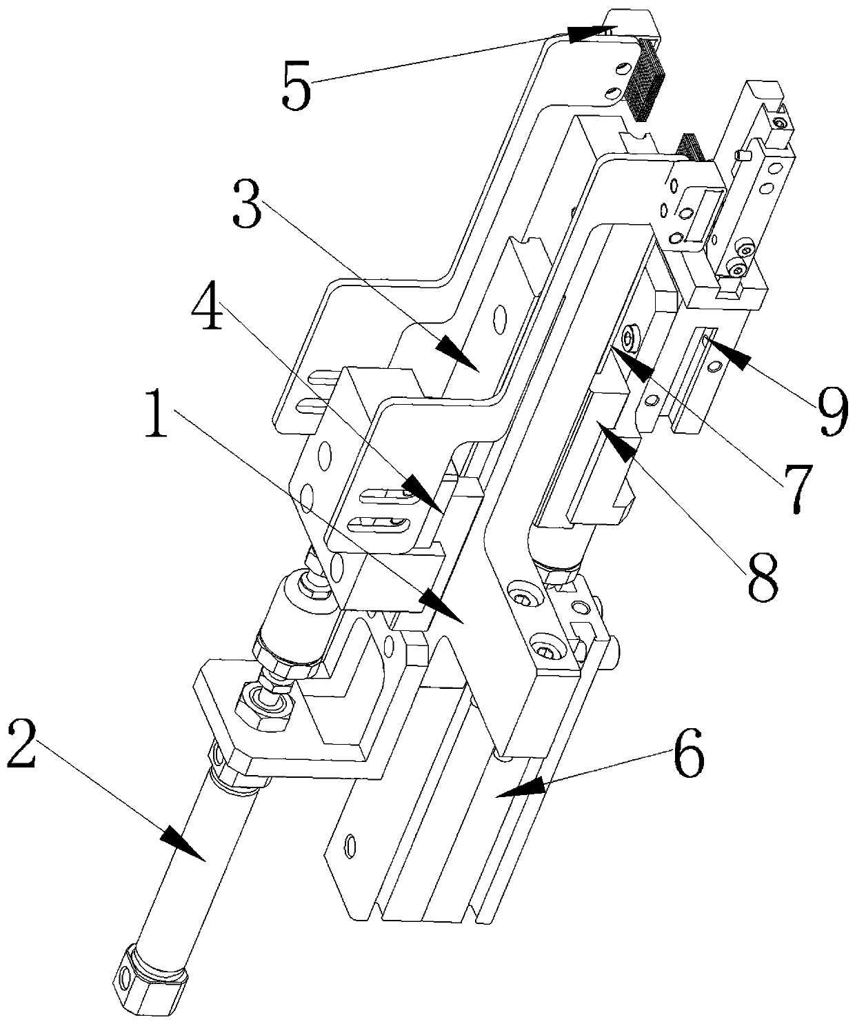
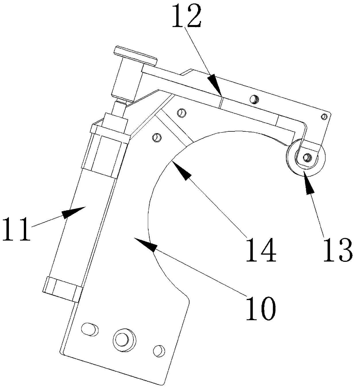
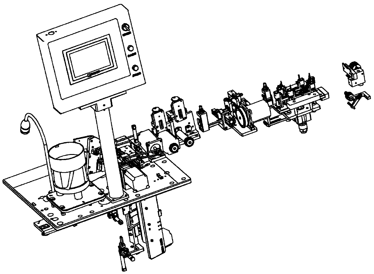
[0024] like Figure 1 to Figure 4 As shown, in this embodiment, the wire distribution mechanism includes a fixed seat 1, a clamping assembly and a wire distribution assembly, and the wire distribution assembly includes a first cylinder 2, a first linear slide rail 3, a first slider 4 and a pair of brush heads 5, the first cylinder 2 and the first linear slide 3 are fixed on the fixed seat 1, the first slider 4 and the piston of the first cylinder 2 The rod is fixedly connected, the first slider 4 is slidingly matched with the first linear slide rail 3, and a pair of brush heads 5 are respectively fixed on both sides of the first slider 4 and the bristles are arranged facing each other. The clamping assembly is fixed on the fixing seat 1, and the clamping assembly clamps the wire end and cooperates with the external twisting mechanism.

[0025] The clamping assembly includes a second cylinder 6, a second linear slide rail 7, a second slider 8 and a gripper cylinder 9, and the ...


PUM


Abstract

The invention aims to provide a wire dividing mechanism, four-wire winding T2 equipment and a wire winding method, wherein the wire dividing mechanism is neat in stranded wires, accurate in segmentation, high in efficiency, low in labor cost and good in thick wire diameter winding effect. The wire dividing mechanism comprises a fixing base, a clamping assembly and a wire dividing assembly, whereinthe wire dividing assembly comprises a first air cylinder, a first linear sliding rail, a first sliding block and a pair of brush heads, the first air cylinder and the first linear sliding rail are fixed on the fixing base, the first sliding block is fixedly connected with a piston rod of the first air cylinder, the first sliding block is in sliding fit with the first linear sliding rail, the pair of brush heads are respectively fixed on two sides of the first sliding block, and bristles are arranged oppositely. The four-wire winding T2 equipment comprises the wire dividing mechanism. The wire winding method is implemented based on the four-wire winding T2 equipment. The wire dividing mechanism, the four-wire winding T2 equipment and the wire winding method are applied to the technical field of network transformer production.

Description

technical field [0001] The invention is applied to the technical field of network transformer production, and in particular relates to a wire splitting mechanism, four-wire winding T2 equipment and a wire winding method. Background technique [0002] Networks are ubiquitous in today's world. Network transformers are the main electronic components of network equipment. The traditional production method of network transformers is manual production. The manual production process includes: manual winding of T1 rings; Fixture, and manually wind the T2 ring. [0003] With the advancement of technology, the winding of the T1 ring can be automatically realized by the machine, but before the winding of the T2 ring, the wire after the T1 ring needs to be segmented and twisted, and the first segment needs to twist the multi-strand enameled wire Form a strand, then separate the enameled wire and twist the remaining wires, and then wind the thick wire segment on the T2 ring, where it is...

Claims


Application Information

Patent Timeline
Patent Type & Authority Applications(China)
IPC IPC(8): H01F41/07H01F41/08
CPCH01F41/07H01F41/08
Inventor 陈新裕吉工亚吴金辉
Owner ZHUHAI HENGNUO SCI & TECH CO LTD
Learn More