
A hydraulic cylinder high pressure protection device

A technology for high pressure protection and hydraulic cylinders, which is applied in the direction of fluid pressure actuation devices, fluid pressure actuation system safety, mechanical equipment, etc. The oil overflow of the overflow valve is not controlled, etc., so as to save the overflow valve and oil overflow pipeline, the structure is simple, and the effect of increasing the system damping

Active Publication Date: 2021-08-17
BEIJING MECHANICAL EQUIP INST
View PDF0 Cites 1 Cited by
  • Summary
  • Abstract
  • Description
  • Claims
  • Application Information

AI Technical Summary

Problems solved by technology

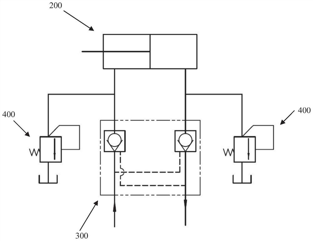
[0006] (1) It is necessary to arrange a separate oil spill pipeline for the relief valve, which makes the pipeline of the hydraulic system more complicated; (2) The oil spill of the relief valve is not controlled, which makes the oil spill at both ends of the hydraulic cylinder unstable and makes the hydraulic pressure The one-sided displacement of the piston in the cylinder exceeds 10mm, which makes it difficult to guarantee the position accuracy of the hydraulic cylinder after the temperature rises and the oil overflows

Method used


Image

  • A hydraulic cylinder high pressure protection device
  • A hydraulic cylinder high pressure protection device
  • A hydraulic cylinder high pressure protection device

Examples


Embodiment Construction

[0045] The preferred embodiments of the present invention will be specifically described below in conjunction with the accompanying drawings, wherein the accompanying drawings constitute a part of the present invention and together with the embodiments of the present invention are used to explain the principles of the present invention and are not intended to limit the scope of the present invention.

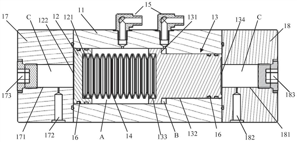
[0046] A specific embodiment of the present invention discloses a hydraulic cylinder high pressure protection device 100 (which may be referred to as the protection device 100 for short), such as Figure 3 to Figure 4 As shown, it includes a valve body 11 and a first piston 12, a second piston 13 and a spring 14 installed in the inner chamber of the valve body 11. The spring 14 is located between the first piston 12 and the second piston 13, and the first piston 12, The outer end of the second piston 13 (the outer side is the end away from the spring) communicates with the rodles...


PUM


Abstract

The invention relates to a high-pressure protection device for a hydraulic cylinder, which relates to the technical field of hydraulic control, and solves the problems in the prior art that the pipelines of the oil spill protection device are redundant and the position accuracy of the hydraulic cylinder is difficult to guarantee after oil spillage. The hydraulic cylinder high pressure protection device of the present invention includes a valve body and a first piston, a second piston and a spring installed in the inner cavity of the valve body; the spring is located between the first piston and the second piston; The ends are respectively connected with the rodless cavity and the rod cavity of the hydraulic cylinder; when the pressure in the rodless cavity and the rod cavity overcomes the initial elastic force of the spring, the hydraulic oil pushes the first piston and the second piston to compress the spring, and the hydraulic oil flows to inside the valve cavity. The hydraulic cylinder high-voltage protection device of the present invention has a simple structure, can be directly installed on the hydraulic cylinder control valve block, saves the overflow valve and the oil overflow pipeline, and simplifies the hydraulic system; The displacement does not exceed 1mm, which ensures the position accuracy of the hydraulic cylinder.

Description

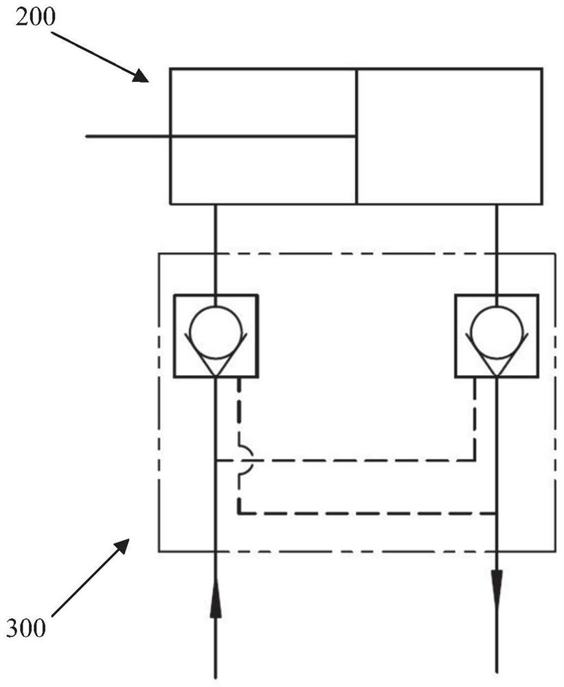
technical field [0001] The invention relates to the technical field of hydraulic control, in particular to a high-voltage protection device for a hydraulic cylinder. Background technique [0002] The hydraulic cylinder is one of the main actuators of the hydraulic system and is widely used in machine tool industry, metallurgical industry, automobile industry, light textile industry, engineering machinery, agricultural machinery and other fields. In the field that requires precise control, such as the field of supporting the mechanism and adjusting the horizontal angle through the hydraulic cylinder, after the hydraulic cylinder moves to the specified position, it needs to be locked. [0003] At present, most hydraulic systems use hydraulic locks to ensure the locking of hydraulic cylinders, such as figure 1 As shown, when the hydraulic cylinder (200) moves to a designated position, the hydraulic pump stops supplying oil, the hydraulic lock (300) is closed, and a closed cavi...

Claims


Application Information

Patent Timeline
Patent Type & Authority Patents(China)
IPC IPC(8): F15B15/14F15B15/20F15B20/00
CPCF15B15/1423F15B15/1433F15B15/1447F15B20/00F15B2215/30
Inventor 牛国贤苏晓岩付丙勤
Owner BEIJING MECHANICAL EQUIP INST
Learn More