ABS plastic recycling and cleaning re-production production line

A technology for recycling ABS plastics and plastics, applied in plastic recycling, mechanical material recycling, recycling technology, etc., can solve problems such as increased production costs, increased workload, and poor dehydration effects

Pending Publication Date: 2020-01-03
江苏嘉天盛再生资源有限公司
View PDF2 Cites 4 Cited by
  • Summary
  • Abstract
  • Description
  • Claims
  • Application Information

AI Technical Summary

Problems solved by technology

[0004] In the above cleaning process, magnetic separation is the most basic and important step, because the recycled waste plastics will inevitably be mixed with magnetic metal pieces such as iron, cobalt, nickel, etc. If these metal pieces are not separated from the material, then Not only will it affect the quality of recycled plastics, but it will also damage the mechanical equipment in the subsequent production process
A magnetic separator whose Chinese patent publication number is CN108972955A includes a frame, a magnet and a motor. The two ends of the frame are respectively provided with a driving roller and a driven roller, and a conveyor belt is connected between the driving roller and the driven roller. , the motor is connected to the driving roller, and the magnet is fixedly arranged in the middle of the frame. Although this design can separate the plastic block and the metal block to a certain extent, since the magnetic separator is separately installed at the entrance of the material conveyor belt, only the magnet Attract the metal blocks in the inlet section to separate the metal blocks from the plastic blocks. When the feeder feeds the conveyor belt, various materials will be stacked together. This magnetic separation method can only absorb lighter metal blocks. And the metal block on the surface, the metal block pressed by the plastic block is difficult to be absorbed, so the separation of the metal block is not thorough enough, and the chute of this kind of magnetic separator is set at both ends, and it must be recovered at both ends The metal block increases the workload. In addition, this separately set magnetic separator also increases the production cost
[0006] The existing dehydration mechanism uses a conventional screw to lift the material and remove the water, but when the material is lifted, the material accumulates on the helical blade, and the cleaning liquid located on the inner side of the helical blade close to the screw shaft is not easy to flow out, and the cleaning solution located on the inside of the helical blade is not easy to flow out. The cleaning liquid on the surface of the material outside the screw blade will partly scatter on the material of the blade below as it rotates, thus causing poor dehydration effect, and the part that slides down with the inner wall of the screw pipe will continue to accumulate at the bottom during continuous production, and finally Into the screw pipe, causing the screw to lose the dehydration function when lifting the material; in addition, after the existing dehydration mechanism dehydrates the material after the first cleaning, there will still be a certain amount of chemical residue on the surface of the material when it enters the second cleaning. In the later stage of continuous production, it will still cause pollution to the second cleaning tank, thus affecting the effect of the second cleaning and separation
[0007] The invention of Chinese Patent Publication No. CN 108332546 A provides a material dehydrator, which includes a frame, a drainage assembly, a feeding cylinder, a feeding motor, a lifting cylinder, a feeding screw, a feeding hopper, a lifting screw, a discharging hopper, a main Although the design of the drainage component of the motor solves the problem of water accumulation at the bottom of the lifting screw, the design of the lifting screw cannot achieve a good dehydration effect, and it cannot solve the influence of residual chemicals on the surface of the material

Method used


Image

  • ABS plastic recycling and cleaning re-production production line
  • ABS plastic recycling and cleaning re-production production line
  • ABS plastic recycling and cleaning re-production production line

Examples


Embodiment 1

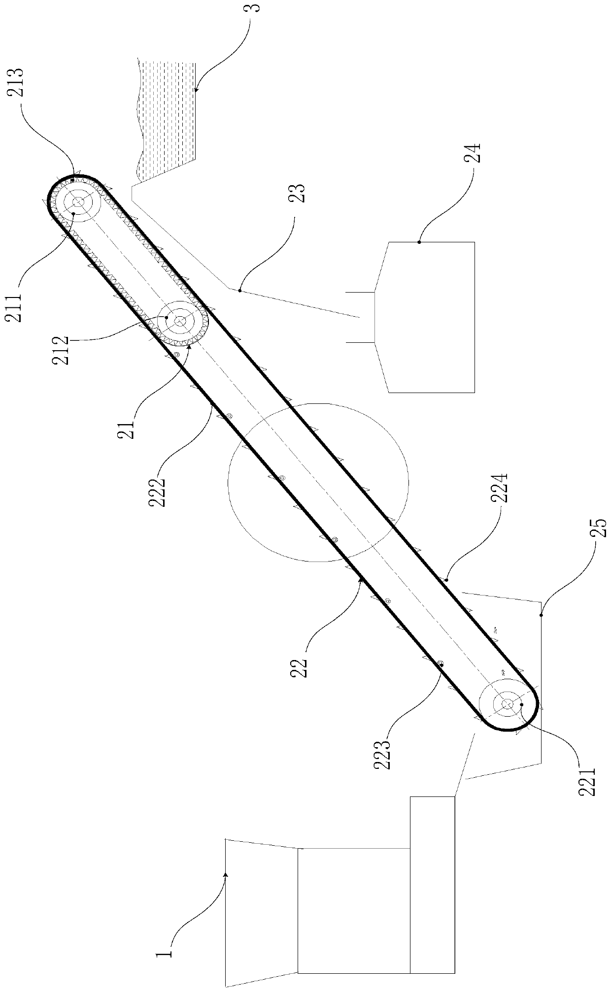
[0051] Such as Figure 2-5 Shown is the magnetic separation device 2 of the present invention, comprising a magnetic separation conveyor belt main body, a magnetic material slideway 23, a magnetic material collection box 24 and a collection tank 25, and the magnetic separation conveyor belt main body includes a magnetic transmission section 21 and a nonmagnetic transmission section 22. In order to better separate the magnetic substances, the main body of the magnetic separation conveyor belt is inclined with a low front end and a high rear end.

[0052]The magnetic transmission section 21 is positioned at the rear end of the magnetic separation conveyor belt main body and shares the same central axis with the magnetic separation conveyor belt main body. The magnetic transmission section 21 includes a drive mounted on an external frame (the frame is a conventional component, not shown in the figure). Roller 211 and first driven roller 212, described driving roller 211 and first...

Embodiment 2

[0057] Such as Figure 6-10 Shown is the first dehydration conveying mechanism 4 of the present invention, comprising a feed pipeline 41, a lifting mechanism and a water receiving tank 46; Filter plate 45 and lifting screw 47.

[0058] The feed pipe 41 is designed in an "L" shape. Such a design can effectively prevent the materials and part of the cleaning fluid from splashing when they fall, and can better gather the materials at the bottom of the lifting mechanism, which can be more thorough. Lift and convey the material efficiently to avoid material loss.

[0059] The screw pipe 42 is designed in the shape of a truncated cone, communicates with the bottom of the feed pipe 41 , and its cross-sectional diameter decreases sequentially from bottom to top, and a discharge pipe 43 is arranged on the upper part of the lower side of the screw pipe 42 .

[0060] The lifting screw 47 is arranged in the inner cavity of the screw pipe 42, and includes a lifting screw shaft 471, a fir...

Embodiment 3

[0068] Such as Figure 11-13 Shown is the spray mechanism 13 of the present invention, including a water receiving mechanism 131, a collection chamber 132, a water pipe placement tank 133, a dehydration material pipe 134, a feed hopper 135, a spray installation seat 136, and a spray head 137.

[0069] The water receiving mechanism 131 is designed as a box with an open top, and three water baffles are provided on the left part of the water receiving mechanism 131 extending upward along its side wall.

[0070] Just above the right part of the water receiving mechanism 131 is fixedly provided with a collection chamber 132, and a water pipe placement groove 133 is formed between the water baffles on the front and rear sides of the water receiving mechanism 131 and the collection chamber 132, so that the external water pump will The water in the water receiving mechanism 131 is taken away.

[0071] Described collection chamber 132 is the box body design of opening below, and the o...


PUM

PropertyMeasurementUnit
thicknessaaaaaaaaaa
widthaaaaaaaaaa
pore sizeaaaaaaaaaa

Abstract

The invention relates to an ABS plastic recycling and cleaning re-production production line. The ABS plastic recycling and cleaning re-production production line comprises a feeding machine, a magnetic separation device, a first cleaning tank, a first dehydration and transfer mechanism, a spraying mechanism, a first conveying mechanism, a second cleaning tank, a second dehydration and transfer mechanism, a drying mechanism, a first plastic cap separation device, a second plastic cap separation device, a second conveying mechanism and a color sorting device from left to right. According to theproduction line, by arranging the first dehydration and transfer mechanism, the spraying mechanism and the first conveying mechanism between the first cleaning tank and the second cleaning tank, cleaning liquid carried with materials from the first cleaning tank is thoroughly removed from the materials which are cleaned for the first time through the first dehydration and transfer mechanism, thenremaining chemicals on the surfaces of the materials are removed through the spraying mechanism, afterwards, the materials are transported into the second cleaning tank through the first conveying mechanism, and the situation that the chemicals on the surfaces of the materials which are cleaned for the first time contaminate the second cleaning tank, and the cleaning and separating effect at thesecond time is influenced accordingly is effectively avoided.

Description

technical field [0001] The invention relates to the technical field of waste plastic recycling and reprocessing, in particular to an ABS plastic recycling, cleaning and reproducing production line. Background technique [0002] In daily life, there are many waste plastics, such as plastic bags, buckets, basins, toys, furniture, stationery and other living utensils and various plastic products, buttons and zippers in the clothing industry, various building components and building tools in building materials. , plastic doors and windows, plaster buckets, etc., agricultural film, pumping pipes, agricultural machinery, fertilizer packaging bags, cement packaging bags, etc., various forms of bearings, gears, cams, different wheels, sealing rings, etc. in the mechanical field Various blades, various water pump impellers, reactors, pipes, containers, pumps, valves, etc. in the chemical field will produce waste plastics. Due to the non-degradability of plastics, these waste plastic...

Claims


Application Information

Patent Timeline
Patent Type & Authority Applications(China)
IPC IPC(8): B29B17/02B29B17/00B03C1/18B08B3/02F26B17/20F26B25/00B01D29/03
CPCB01D29/03B03C1/18B08B3/022B29B17/00B29B17/02B29B2017/001B29B2017/0015B29B2017/0272F26B17/20F26B25/00Y02W30/52Y02W30/62
Inventor 刘仕明
Owner 江苏嘉天盛再生资源有限公司
Why Eureka
Try Eureka