Mechanical chain surface oily matter cleaning equipment for rotating cleaning during meshing

A technology for cleaning equipment and equipment, which is applied in the direction of cleaning methods using tools, cleaning methods and utensils, and removing smoke and dust. It can solve the problems of poor chain flexibility, large resistance, and chain wall wear, and achieve the effect of flexibility

Inactive Publication Date: 2020-01-03
凌金霞
View PDF0 Cites 0 Cited by
  • Summary
  • Abstract
  • Description
  • Claims
  • Application Information

AI Technical Summary

Problems solved by technology

[0004] In view of the deficiencies in the prior art, the purpose of the present invention is to provide a mechanical chain surface oil cleaning device that rotates and cleans when meshing, so as to solve the problem in the prior art that the mechanical chain is a combination of multiple smaller parts. The oil stained in the gap between the two chains is relatively stubborn, and the traditional brush can completely eradicate it, and under the action of the characteristics of the brush itself, it changes when it moves, so Unable to penetrate into the innermost part of the chain gap, resulting in some oil in the gap between the chain joints after cleaning, resulting in poor flexibility of the chain and greater resistance during operation. Larger, so there are more oil around it, and under long-term accumulation, it will even be filled, resulting in the failure of normal meshing, while the traditional cleaning equipment is mechanically directly cleaning the oil in the chain frame hole. If it is cleaned, it is more likely to cause wear on the chain wall, thereby shortening its service life.

Method used


Image

  • Mechanical chain surface oily matter cleaning equipment for rotating cleaning during meshing
  • Mechanical chain surface oily matter cleaning equipment for rotating cleaning during meshing
  • Mechanical chain surface oily matter cleaning equipment for rotating cleaning during meshing

Examples


Embodiment Construction

[0027] In order to make the technical means, creative features, goals and effects achieved by the present invention easy to understand, the present invention will be further described below in conjunction with specific embodiments.

[0028] Such as Figure 1-Figure 6 As shown, the present invention provides a technical scheme of a mechanical chain surface oil cleaning device that is rotated and cleaned during meshing:

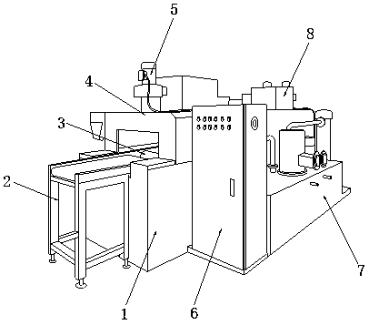
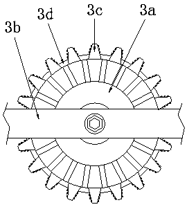
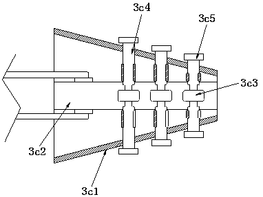
[0029] Such as Figure 1-Figure 2 As shown in the figure, a mechanical chain surface oil cleaning device that rotates and cleans when meshing, its structure includes a device main body 1, a conveyor frame 2, a chain cleaning device 3, a dust cover 4, a drive motor 5, a control cabinet 6, a liquid Tank 7, dryer 8, the conveying frame 2 is arranged on the front surface of the equipment main body 1 and extends into it, and the chain internal cleaning device 3 is arranged on the inner upper part of the equipment main body 1 and is located behind the extending end ...


PUM


Abstract

The invention discloses mechanical chain surface oily matter cleaning equipment for rotating cleaning during meshing. The equipment structurally comprises an equipment body, a conveying frame, an in-chain cleaning device, a dust blocking cover, a driving motor, a control cabinet, a liquid tank box and a drying machine. The equipment has the beneficial effects that under the cooperation of a roughlayer and an S-bend pipe, oily matter in meshed rotating chains is removed through continuous rotation of rotating columns, and the loosening and falling oily matter is treated in a centralized mode under the action of adsorption airflow inside the S-bend pipe, so that the oily matter is prevented from adhering to equipment parts. Meanwhile, the oily matter adhering to the edge walls of the chainsis further scraped through scraping plates, so that the inner walls of the chains are prevented from being abraded when brushes are cleaned. According to the equipment, caking in a seam of the jointof the two chains falls off under the friction action of an iron coil by using an arranged inner rubbing structure, so that the flexibility of the joint of the chains is achieved, and the situation that when the chains are used, the chain running resistance is large due to the oily matter in the seam of the joint is avoided.

Description

technical field [0001] The invention relates to the field of cleaning equipment, more precisely, it relates to a cleaning equipment for oil on the surface of a mechanical chain that rotates and cleans when meshing. Background technique [0002] As one of the core parts of the power start of mechanical equipment, the chain is mainly used for mechanical tradition and traction, because it needs to be continuously operated and meshed with other parts, and it needs to be regularly oiled and lubricated to ensure The flexibility of the chain during operation, and under the long-term operation of the chain and the oily effect, a layer of oil will be formed on the surface, which will cause greater resistance during the transmission process of the equipment, which will affect the normal operation of the overall equipment, so it is necessary Clean the mechanical chain regularly to ensure the flexibility of the chain during operation. [0003] However, because the mechanical chain is a...

Claims


Application Information

Patent Timeline
IPC IPC(8): B08B1/02B08B13/00B08B15/04
CPCB08B13/00B08B15/04B08B1/165B08B1/20
Inventor 凌金霞
Owner 凌金霞
Why Eureka
Try Eureka