Rotary switch for controlling the vehicle's parking brake
What is Al technical title?
Al technical title is built by PatSnap Al team. It summarizes the technical point description of the patent document.
A technology of rotary switch and braking device, which is applied in the direction of mechanical control device, device for preventing/limiting/recovering the movement of parts of the control mechanism, manual starting device, etc. problem, to achieve the effect of easy measurement and easy setting
Active Publication Date: 2022-06-28
KNORR-BREMSE SYST FUER NUTZFAHRZEUGE GMBH
View PDF9 Cites 0 Cited by
Summary
Abstract
Description
Claims
Application Information
AI Technical Summary
This helps you quickly interpret patents by identifying the three key elements:
Problems solved by technology
Method used
Benefits of technology
Problems solved by technology
[0007] Such an actuating device would on the one hand be complex in construction and on the other hand be incapable of Intuitive to operate or difficult to operate
Method used
Image
Click on the blue label to locate the original text in one second.
Reading with bidirectional positioning of images and text.
Examples
Embodiment Construction
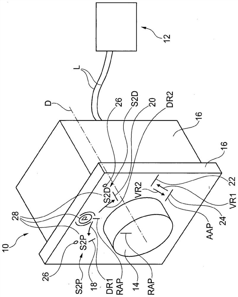
[0039] figure 1 A schematic perspective view of a first embodiment of a rotary switch 10 according to the invention and an electronic parking brake device 12 according to the invention is shown.
[0040] The rotary switch 10 is connected to the electronic parking brake device 12 via two wires L.
[0041] The rotary switch 10 may also be connected to the electronic parking brake device 12 through one wire L or two or more wires L.
[0042] The rotary switch 10 also has a knob 14 and a knob counterpart 16 .
[0043] The knob 14 and the knob counterpart 16 are rotatably connected to each other and twistable relative to each other about a common axis of rotation D.
[0044] For this purpose, the rotary knob 14 is rotatably mounted on the rotary knob counterpart 16 and protrudes beyond the rotary knob counterpart 16 with a cylindrical projection.
[0045] The knob 14 is twistable relative to the knob counterpart 16 about the first rotational direction DR1 and about the second ro...
PUM
Abstract
The invention relates to a rotary switch (10, 110, 210, 310) for controlling an electronic parking brake device (12, 112, 212, 312) of a commercial vehicle, having a knob (14, 114, 214, 314) and the knob counterpart (16, 16, 216, 316), the knob (14, 114, 214, 314) and the knob counterpart (16, 116, 216, 316) are rotatably connected to each other and can rotate about a common axes (D, 1D, 2D, 3D) are twisted relative to each other, the knobs (14, 114, 214, 314) are additionally able to rotate relative to the counterpart ( 16, 116, 216, 316) to move axially, the rotary switch (10, 10, 210, 310) has at least one manipulation switch state (S2P, 1S2P, 2S2P, 3S2P) and at least one release switch state (S2D, 1S2D, 2S2D, 3S2D), manipulating the switch state (S2P, 1S2P, 2S2P, 3S2P) by the knob (14, 114, 214, 314) in the first rotation direction (DR1, 1DR1, 2DR1, 3DR1) and / or The movement of the knob (14, 1, 14, 214, 314) along the first axis of the first movement direction (VR1, 1, VR1, 2VR1, 3VR1) causes the release of the switch state (S2D, 1S2D, 2S2D, 3S2D) A second rotational movement by the knob (14, 14, 214, 314) in the second direction of rotation (DR2, 1DR2, 2DR2, 3DR2) and / or a second rotational movement of the knob (14, 14, 214, 314) in the first direction of movement (VR1 , 1VR1, 2VR1, 3VR1) caused by the second axial movement.
Description
technical field [0001] The invention relates to a rotary switch for controlling an electric parking brake of a vehicle, in particular a commercial vehicle, having a rotary knob and a rotary knob counterpart, wherein the rotary knob and the rotary knob counterpart are rotatably connected to one another. Background technique [0002] In the course of the progressive electrification of commercial vehicle parking brakes, alternative actuation concepts can be used especially in conjunction with electronic parking brakes, since the actuation of electronic parking brakes will often be able to be electrically operated in the future. structure. Thus, on the one hand, an expensive and structurally demanding pneumatic actuating device can be replaced by a structurally simpler electrical actuating device, and on the other hand, greater degrees of freedom can be achieved with regard to design (eg rotary switch) and operating principle. [0003] Such actuating devices are known from the ...
Claims
Application Information
Patent Timeline
Application Date:The date an application was filed.
Publication Date:The date a patent or application was officially published.
First Publication Date:The earliest publication date of a patent with the same application number.
Issue Date:Publication date of the patent grant document.
PCT Entry Date:The Entry date of PCT National Phase.
Estimated Expiry Date:The statutory expiry date of a patent right according to the Patent Law, and it is the longest term of protection that the patent right can achieve without the termination of the patent right due to other reasons(Term extension factor has been taken into account ).
Invalid Date:Actual expiry date is based on effective date or publication date of legal transaction data of invalid patent.