
Aerosol-generating article having fibrous filter segment

An aerosol generation and aerosol technology, which is applied in the fields of e-liquid filter elements, smoker supplies, textiles and papermaking, etc., can solve the problems of complicated or expensive manufacturing of aerosol cooling elements, and achieve the effect of eliminating the need and reducing the number of manufacturing steps

Pending Publication Date: 2019-12-31
PHILIP MORRIS PROD SA
View PDF7 Cites 4 Cited by
  • Summary
  • Abstract
  • Description
  • Claims
  • Application Information

AI Technical Summary

Problems solved by technology

However, aerosol cooling elements can be relatively complex or expensive to manufacture

Method used


Image

  • Aerosol-generating article having fibrous filter segment
  • Aerosol-generating article having fibrous filter segment
  • Aerosol-generating article having fibrous filter segment

Examples


Embodiment Construction

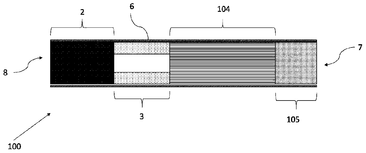
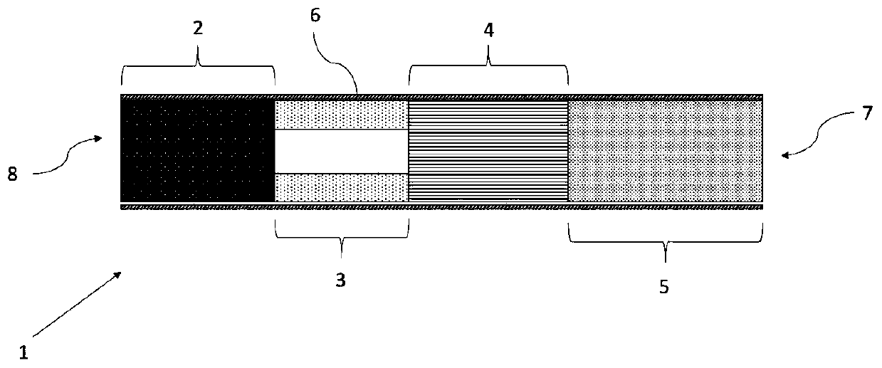
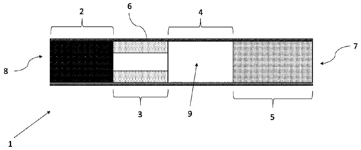
[0082] figure 1 A prior art aerosol-generating article 100 is illustrated. Article 1 comprises four elements. The elements are: an aerosol generating substrate 2, a support element 3, an aerosol cooling element 104 and a filter segment 105 comprising cellulose acetate fibers having a denier per filament of about 8.

[0083] These four elements are arranged one behind the other and in coaxial alignment and are assembled from the rolling paper 6 to form a rod. The strip has a mouth end 7 which the user inserts into his or her mouth during use and a distal end 8 which is located at the end of the strip opposite the mouth end 7 . Elements located between the oral end 7 and the distal end 8 may be described as being upstream of the oral end 7 , or alternatively downstream of the distal end 8 . When assembled, the bar had a length of 52 mm and a diameter of 7.2 mm. The filter segment 105 has a length of 8 mm and the aerosol cooling element 104 has a length of 17 mm.

[0084] ...


PUM


Abstract

A aerosol-generating article (1) comprising a plurality of components assembled within a wrapper to form a rod having a mouth end (7) and a distal end (8) upstream from the mouth end. The plurality ofcomponents comprises an aerosol-forming substrate (2) and a filter segment downstream (5) of the aerosol-forming substrate, the filter segment comprising fibres of at least about 12 denier per filament.

Description

technical field [0001] The present invention relates to an aerosol-generating article comprising an aerosol-forming substrate for generating an inhalable aerosol upon heating. Aerosol-generating articles in which an aerosol-forming substrate, such as a tobacco-containing substrate, is heated rather than combusted are known in the art. The purpose of such heated aerosol-generating articles is to reduce known harmful smoke constituents produced by the combustion and thermal degradation of tobacco in conventional cigarettes. Background technique [0002] Traditional smoking is ignited when the user applies a flame to one end of the cigarette and draws air through the other end. The localized heat provided by the flame and oxygen in the air drawn by the cigarette causes the tip of the cigarette to ignite and the resulting combustion produces inhalable smoke. In contrast, in heated aerosol-generating articles, the inhalable aerosol is typically generated by transferring heat fr...

Claims


Application Information

Patent Timeline
Patent Type & Authority Applications(China)
IPC IPC(8): A24D3/04A24F47/00A24D3/17
CPCA24D3/17A24D1/20A24D1/22A24F40/10A24F40/46A24D3/04A24D3/063A24D3/10A24D3/14A24F13/06D21H5/16
Inventor J·乌瑟瑞
Owner PHILIP MORRIS PROD SA
Learn More