
Dynamic and static submarine optical cable connector box

A submarine optical cable and splice box technology, which is applied in the directions of light guide, optics, optical components, etc., can solve the problems that the splice box cannot meet the strength requirements of submarine optical cable laying, large construction risks, and processing difficulties.

Pending Publication Date: 2019-12-31
JIANGSU HENGTONG MARINE CABLE SYST CO LTD
View PDF0 Cites 6 Cited by
  • Summary
  • Abstract
  • Description
  • Claims
  • Application Information

AI Technical Summary

Problems solved by technology

[0007] (1) Most of the existing joint boxes are made of 2507 duplex stainless steel, which is expensive and difficult to process;
[0008] (2) The fixing method of the pressure armor steel wire is only suitable for tensile resistance in a static environment, but in a dynamic environment, under the action of a force value exceeding 6 tons, fatigue failure is relatively prone to occur;
[0009] (3) The tensile strength generated during the laying process is relatively large, and the existing splice box cannot meet the laying strength requirements of submarine optical cables, and there is a large construction risk;
[0010] (4) Its overall structure is suitable for the connection of static submarine optical cables, which will cause the dynamic balance of dynamic submarine optical cables to fail

Method used


Image

  • Dynamic and static submarine optical cable connector box
  • Dynamic and static submarine optical cable connector box

Examples


Embodiment Construction

[0025] The preferred embodiments of the present invention are described in detail below, so that the advantages and features of the present invention can be more easily understood by those skilled in the art, so as to define the protection scope of the present invention more clearly.

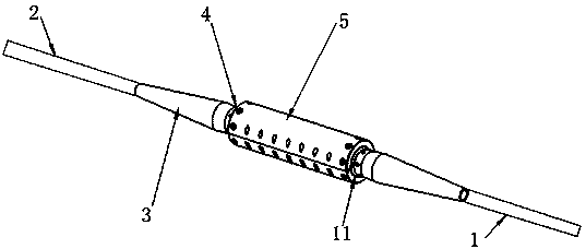
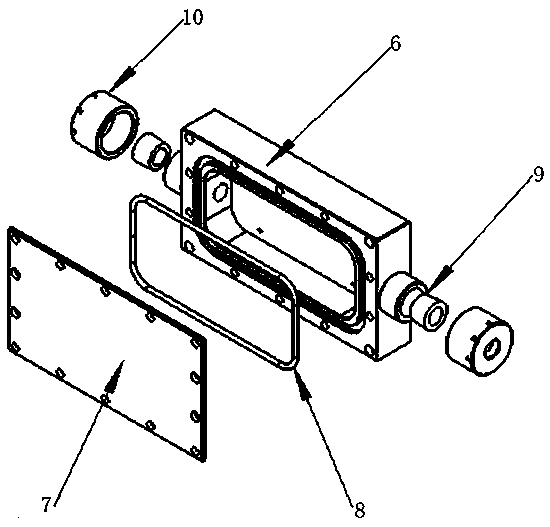
[0026] The invention is a dynamic and static submarine optical cable splice box, such as figure 1 As shown, there are anti-bending devices 3 respectively sleeved on the connection end sides of the dynamic submarine optical cable 1 and the static submarine optical cable 2 to effectively ensure the bending degree of the dynamic submarine optical cable 1 and the static submarine optical cable 2, and the end of the static submarine optical cable 2 The steel wire armor device 4 realized by two layers of armored steel wire armor is clamped and fixed on the cylinder 5, and the steel wire armor device 4 is fixed by screw locking. The dynamic submarine optical cable 1 is made of glue 11. The method reali...


PUM


Abstract

The present invention discloses a dynamic and static submarine optical cable connector box. The dynamic and static submarine optical cable connector box comprises a cylinder, a steel wire metal clad pressing device, and benders; the benders respectively sleeve on the sides of the ends of a dynamic submarine optical cable and a static submarine optical cable; the dynamic submarine optical cable islocked on the cylinder by means of glue filling; the static submarine optical cable is correspondingly arranged on the cylinder through the steel wire metal clad pressing device; a Haval-type structure is used for the cylinder; the cylinder is further correspondingly provided with an optical fiber box; and the cores of the dynamic submarine optical cable and the static submarine optical cable passthrough the cylinder and the optical fiber box, and are fused in the optical fiber box. According to the dynamic and static submarine optical cable connector box provided by the present invention, the cost is reduced; the rapid integration capability of the product is realized; by using the optical fiber box sealing method, the product structure size is reduced and the construction is facilitated; glue filling is used to tightly locking the dynamic submarine optical cable steel wire, metal clad pressing is used to tightly locking the static submarine optical cable steel wire, and mechanical structure design is used to prevent the torsion of the static cable from damaging the dynamic balance of the dynamic cable.

Description

technical field [0001] The invention relates to a dynamic and static submarine optical cable joint box. Background technique [0002] The dynamic submarine optical cable is the lifeline connecting the floating platform and the underwater production system, providing optical fiber information for the underwater production system of the offshore oil production platform, and providing a data transmission channel for the underwater production system. As a special signal transmission medium, dynamic submarine optical cable plays an indispensable role in various fields, but it is expensive and not suitable for long-distance use. Usually, dynamic submarine optical cable is used in conjunction with static submarine optical cable, so it needs to be The dynamic submarine optical cable is mechanically connected with the static submarine optical cable, and the dynamic and static submarine optical cable joint box is designed accordingly. The main functions of the dynamic and static subm...

Claims


Application Information

Patent Timeline
IPC IPC(8): G02B6/44
CPCG02B6/4446G02B6/44384
Inventor 杨垒许人东徐林王雄石明强
Owner JIANGSU HENGTONG MARINE CABLE SYST CO LTD
Learn More