
A current detection circuit, chip and current detection method for speaker protection

A current detection circuit and current detection technology, applied in the direction of measuring current/voltage, using digital measurement technology to measure, only measuring current, etc., can solve the problem of reducing the output power of Class_D, reducing the overall efficiency of Class_D, and not being able to maximize the loudspeaker Power performance and other issues

Active Publication Date: 2022-02-01
SHANGHAI AWINIC TECH CO LTD
View PDF5 Cites 0 Cited by
  • Summary
  • Abstract
  • Description
  • Claims
  • Application Information

AI Technical Summary

Problems solved by technology

[0003] Since portable devices are compact and easy to carry, the built-in speaker cavity is often relatively small. When the power amplifier is playing a song with a large volume, especially a song with a large bass, the speaker cavity may move away due to the displacement of the diaphragm. The speaker is damaged due to the large size or the temperature of the speaker is too high
[0004] When the output power of the Class_D audio power amplifier is very large, especially when the top is clipped, the current of the speaker is very large. At this time, the current detection module needs to accurately detect the current of the speaker for protection. However, when clipping occurs, the speaker output terminal VON Or VOP may appear high level or low level in several PWM (Pulse Width Modulation, pulse width modulation) cycles, some current detection methods are not suitable, usually need Class_D plus anti-clipping distortion function, that is, active limitation The output power of Class_D prevents the output from clipping. VON and VOP will have a square wave in each PWM cycle. However, this will reduce the output power of Class_D and cannot maximize the high-power performance of the speaker.
[0005] Moreover, some current detection methods need to add a detection circuit, such as connecting a detection resistor in series at the source end of the power tube, so as to sample the voltage on the detection resistor and realize current detection. However, the added detection circuit increases the power loss, reducing the overall efficiency of the Class_D

Method used


Image

  • A current detection circuit, chip and current detection method for speaker protection
  • A current detection circuit, chip and current detection method for speaker protection
  • A current detection circuit, chip and current detection method for speaker protection

Examples


Embodiment Construction

[0067] The following will clearly and completely describe the technical solutions in the embodiments of the present invention with reference to the accompanying drawings in the embodiments of the present invention. Obviously, the described embodiments are only some, not all, embodiments of the present invention. Based on the embodiments of the present invention, all other embodiments obtained by persons of ordinary skill in the art without making creative efforts belong to the protection scope of the present invention.

[0068] In order to make the above objects, features and advantages of the present invention more comprehensible, the present invention will be further described in detail below in conjunction with the accompanying drawings and specific embodiments.

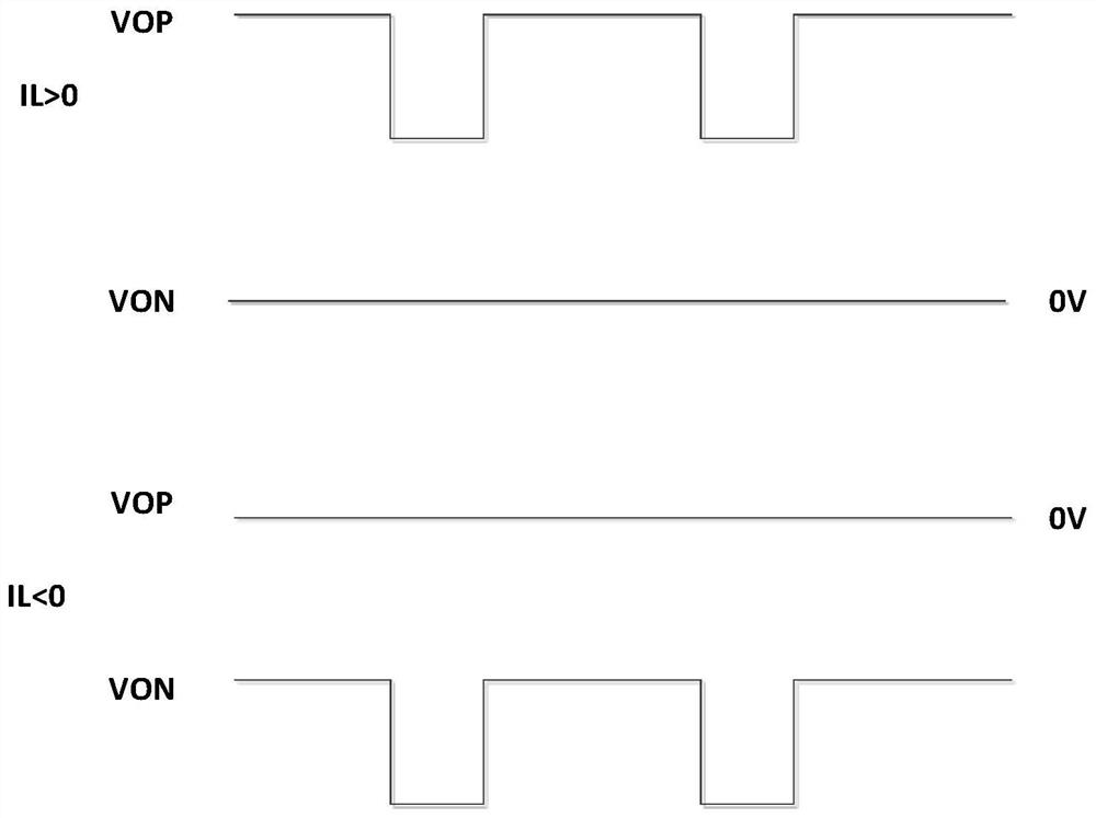
[0069] refer to figure 1 , figure 1 It is a schematic diagram of an output waveform in the Class_D tri-state modulation mode provided by the embodiment of the present invention.

[0070] Such as figure 1 As sho...


PUM


Abstract

This application provides a current detection circuit, chip and current detection method for speaker protection. Through the current detection module, the power tube current mirroring technology is used to realize the sampling of the speaker current, and convert the current into a voltage to output the first voltage. signal and the second voltage signal, the design of this circuit will not increase the power loss of the Class_D circuit. And, combine the analog-to-digital converter to convert the first voltage signal and the second voltage signal into PDM codes to calculate the current value parameters on the speaker, the effective bit can be as high as 13 bits, even if the output power of Class_D is very large , there is no need to increase the anti-slipping distortion function, and the speaker current can be detected normally.

Description

technical field [0001] The invention relates to the technical field of semiconductor integrated circuits, and more specifically, relates to a current detection circuit, a chip and a current detection method for speaker protection. Background technique [0002] Class_D audio power amplifier is widely used in portable devices such as Bluetooth speakers and mobile phones due to its advantages of high efficiency, low heat generation and good performance. [0003] Since portable devices are compact and easy to carry, the built-in speaker cavity is often relatively small. When the power amplifier is playing a song with a large volume, especially a song with a large bass, the speaker cavity may move away due to the displacement of the diaphragm. The speaker is damaged due to the large size or the temperature of the speaker is too high. [0004] When the output power of the Class_D audio power amplifier is very large, especially when the top is clipped, the current of the speaker i...

Claims


Application Information

Patent Timeline
Patent Type & Authority Patents(China)
IPC IPC(8): G01R19/25
CPCG01R19/25H04R3/007G01R19/0092G01R19/2509G01R19/0038G01R19/16528
Inventor 杨志飞张海军杜黎明程剑涛孙洪军
Owner SHANGHAI AWINIC TECH CO LTD
Learn More