
White light LED circuit and method for controlling average current of white light LED

A technology of LED circuit and white light, applied in the direction of circuit, circuit layout, electroluminescent light source, etc., can solve the problem of increasing power loss, achieve the effect of increasing power loss and improving control accuracy

Active Publication Date: 2013-01-23
CHENGDU MONOLITHIC POWER SYST
View PDF0 Cites 0 Cited by
  • Summary
  • Abstract
  • Description
  • Claims
  • Application Information

AI Technical Summary

Problems solved by technology

This current control method has high precision, but the sampling resistor connected in series increases additional power loss

Method used


Image

  • White light LED circuit and method for controlling average current of white light LED
  • White light LED circuit and method for controlling average current of white light LED
  • White light LED circuit and method for controlling average current of white light LED

Examples


Embodiment Construction

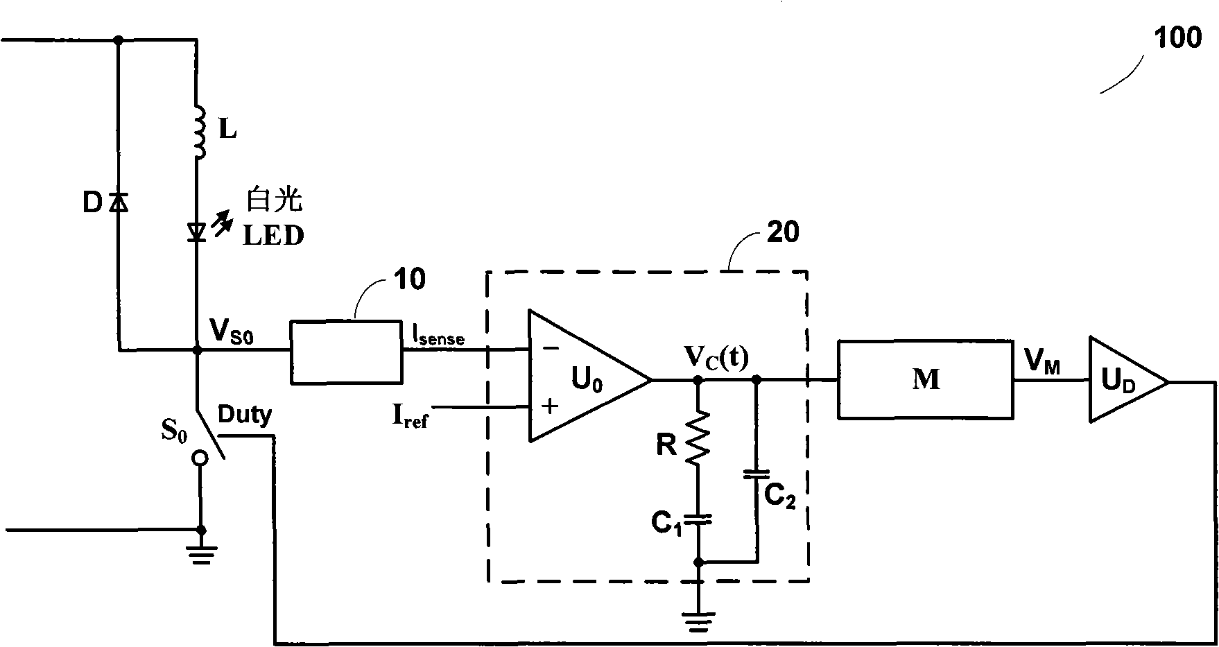
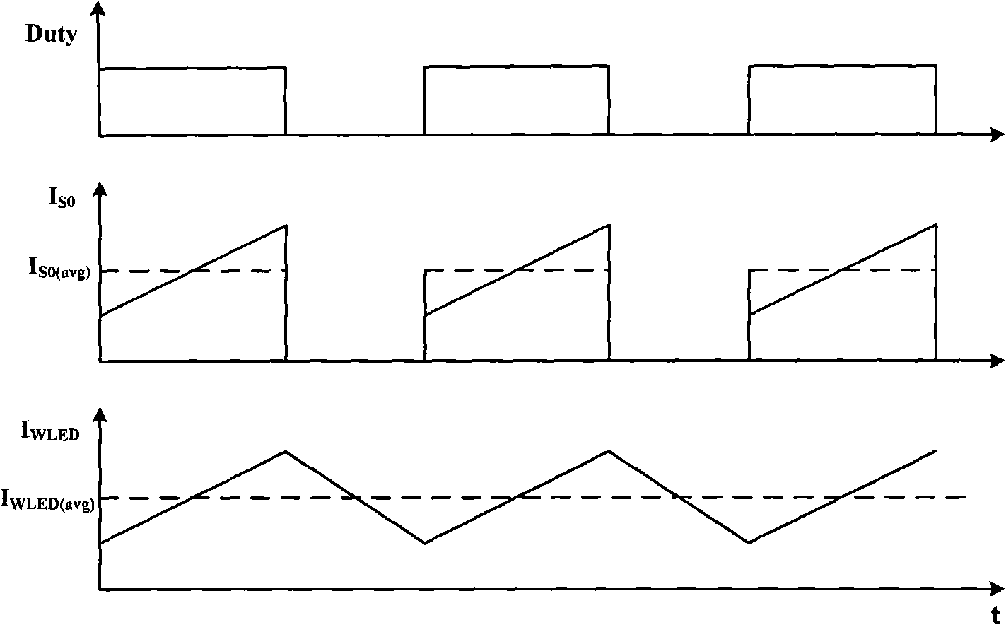
[0039] Such as figure 2 Shown is a circuit 100 for controlling the average current of a white light LED with high precision according to the present invention. Such as figure 2 As shown, the circuit 100 consists of an input V IN , main switching tube S 0 , a freewheeling diode D, an inductor L, and a typical buck circuit composed of a white LED, that is, the white LED is first connected in series with the inductor L and then connected in parallel with the freewheeling diode D, and then connected in parallel with the main switch S 0 connected in series across the input. The circuit 100 further includes a sampling circuit 10, a compensation circuit 20, a modulation circuit M and a driving circuit U D . The input terminal of the sampling circuit is connected to the main switch tube S 0 The upper end of which the output signal is delivered to one input end of the compensation circuit 20; the other input end of the compensation circuit 20 receives the reference signal I re...


PUM


Abstract

An LED circuit is disclosed. The circuit senses the average current flowing through the LED. The sensed signal is compensated and modulated. The modulated signal is then used to control the ON / OFF state of a switch that supplies power to the LED.

Description

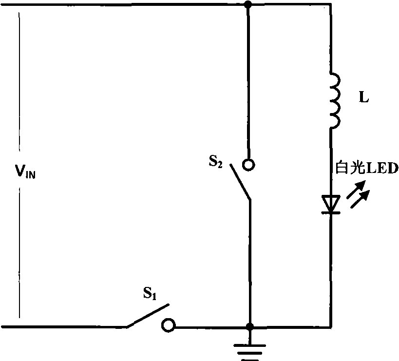
technical field [0001] The present invention relates to an electronic circuit, and more specifically, the present invention relates to a white light LED circuit in the electronic circuit and a method for accurately controlling the average current flowing through the white light LED. Background technique [0002] Due to its many advantages such as no pollution, long life, vibration resistance and impact resistance, white light LED has attracted much attention in the lighting field and has been applied to a certain extent. [0003] Such as figure 1 The circuit shown is a typical application of white LED in buck circuit. When switch S 1 is turned on, switch S 2 is shut down, the input V IN , inductor L, white LED, switch S 1 A current loop is formed, and the current of the inductor L and the white LED increases; when the switch S 1 is turned off, switch S 2 When turned on, inductor L, white LED, switch S 2 A current loop is formed, and the current of the inductor L and ...

Claims


Application Information

Patent Timeline
Patent Type & Authority Patents(China)
IPC IPC(8): H01L25/00H05B37/00H05B37/02F21V23/00F21Y101/02
CPCH05B33/0818H05B45/375
Inventor 任远程杜磊黄勇
Owner CHENGDU MONOLITHIC POWER SYST
Learn More