
Hydraulic controlled clutch and speed variator

A clutch and hydraulic technology, applied in the direction of clutches, fluid-driven clutches, non-mechanical drive clutches, etc., can solve the problems of strong shifting frustration, complex structure, small load torque, etc., and achieve stable power engagement and separation, and high transmission efficiency , The effect of fast shifting speed

Pending Publication Date: 2019-12-31
尚尔航
View PDF0 Cites 0 Cited by
  • Summary
  • Abstract
  • Description
  • Claims
  • Application Information

AI Technical Summary

Problems solved by technology

For example: (1) AT transmission has mature technology, good ride comfort, and high torque capacity; however, due to the complex structure, it is difficult to produce, so the manufacturing cost of AT transmission is relatively high
In addition, because the AT transmission includes a hydraulic torque converter component, the power transmission efficiency is slightly lower; (2) The CVT continuously variable transmission has better smoothness, but the disadvantage is that the load torque is small and the life of the power transmission belt is limited, which is generally only suitable for low-emission vehicles; (3) The transmission efficiency of the dual-clutch transmission is relatively high, but judging from the actual use effect, the shifting feeling is strong and the driving experience is not good

Method used


Image

  • Hydraulic controlled clutch and speed variator
  • Hydraulic controlled clutch and speed variator
  • Hydraulic controlled clutch and speed variator

Examples


Embodiment Construction

[0029] In order to describe the technical content, structural features, achieved goals and effects of the present invention in detail, the following will be described in detail in conjunction with the embodiments and accompanying drawings.

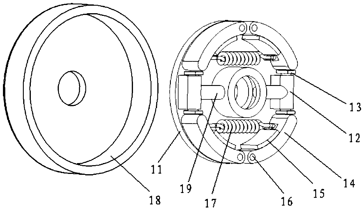
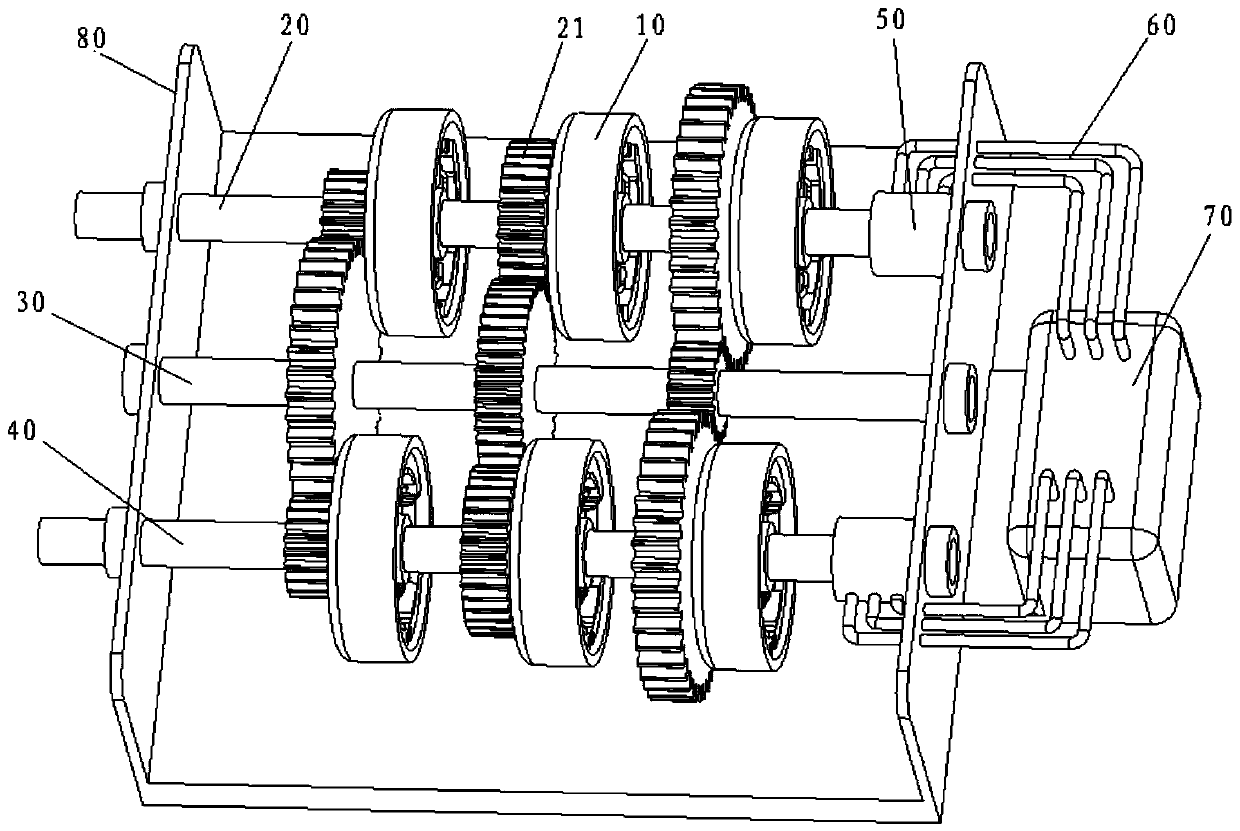
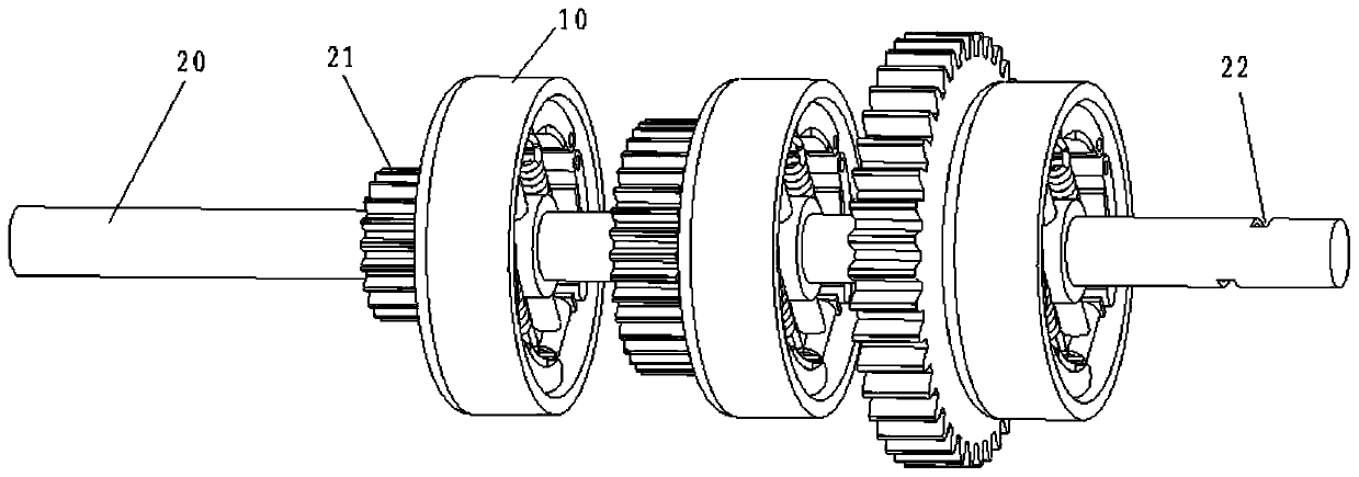
[0030] refer to figure 1 and figure 2 , a specific embodiment of the present invention is: a hydraulically controlled clutch, the clutch 10 includes,

[0031] The brake drum 18 and the brake assembly matching the shape and size of the brake drum 18, the brake assembly is placed inside the brake drum 18, the brake assembly includes a brake base plate 11, a brake cylinder 12 , hydraulic pipeline 19, brake shoe 14, brake shoe baffle 15, support pin 16 and return spring 17;

[0032] There are four brake shoes 14, and the brake shoes 14 are respectively pivotally connected with the support pin 16 along the edge of the brake base plate 11; the brake shoe baffle plate 15 is fixed on the brake base plate 11, and contact with the inner surface ...


PUM


Abstract

The invention provides a hydraulic controlled clutch and a speed variator. The clutch comprises a brake drum and brake assemblies, wherein the brake assemblies are placed inside the brake drum, and the brake assemblies comprise a brake base disc, brake branch pumps, a hydraulic pipeline, brake shoes, brake shoe baffles, support pins and return springs; four brake shoes are provided which are correspondingly connected with the supporting pins along the edge of the brake base disc in a pivoted mode, the brake shoe baffles are fixed on the brake base disc and make contact with the inner side faces of the brake shoes to limit the brake shoes; and the outer side faces of the brake shoes are separated from / make contact with the inner side face of the brake drum so as to realize the separation / connection between the brake shoes and the brake drum, each brake branch pump is provided with two pistons, the end parts of the pistons abut against the end parts, far away from one ends of the supporting pins, of the brake shoes, the pistons are moved through the hydraulic driving in the hydraulic pipeline, and the pistons push the brake shoes to expand outwards to realize the separation / connection between the brake assemblies and the brake drum. According to the technical scheme, the transmission stability of the clutch can be improved.

Description

technical field [0001] The invention relates to a clutch and a speed change device, in particular to a hydraulic control clutch and a speed change device. Background technique [0002] A transmission is a device that changes the running speed of a car and consists of many gears with different diameters. The transmission is mainly used to change the torque and speed of the engine crankshaft to meet the needs of different driving wheel traction and vehicle speed requirements under different driving conditions such as starting, accelerating, driving, and overcoming various road obstacles. At present, the mainstream automatic transmissions used in automobiles include AT, CVT and dual-clutch and other types. Each automatic transmission has its pros and cons. For example: (1) AT transmission has mature technology, good ride comfort, and large torque capacity; however, due to its complex structure, it is difficult to produce, so the manufacturing cost of AT transmission is relati...

Claims


Application Information

Patent Timeline
Patent Type & Authority Applications(China)
IPC IPC(8): F16D25/065F16D25/12F16H3/08F16H3/091
CPCF16D25/065F16D25/14F16D2300/14F16H3/08F16H3/091F16H2003/0826F16H2200/0065
Inventor 尚尔航
Owner 尚尔航
Learn More