
Quick support formwork for pipe gallery and construction method thereof

A formwork, rapid technology, applied in artificial islands, water conservancy projects, infrastructure engineering, etc., to achieve the effect of simplifying the construction process, reducing construction links, and simplifying the internal support structure

Pending Publication Date: 2019-12-31
中铁隧道集团二处有限公司 +1
View PDF0 Cites 2 Cited by
  • Summary
  • Abstract
  • Description
  • Claims
  • Application Information

AI Technical Summary

Problems solved by technology

[0004] The purpose of the present invention is to solve the practical difficulties existing in the above-mentioned construction, to provide a simple structure, easy to operate, fast, efficient, safe and reliable rapid support formwork and its construction method for the construction of the pipe gallery, which greatly simplifies the construction of the pipe gallery The process of supporting the formwork effectively solves the problems existing in the technical background

Method used


Image

  • Quick support formwork for pipe gallery and construction method thereof
  • Quick support formwork for pipe gallery and construction method thereof
  • Quick support formwork for pipe gallery and construction method thereof

Examples


Embodiment 1

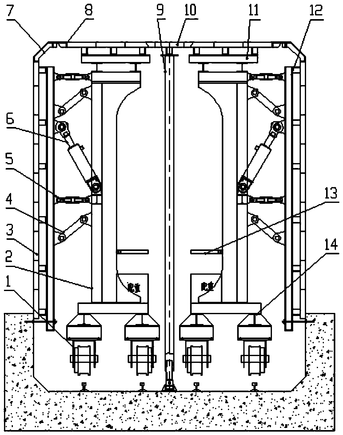
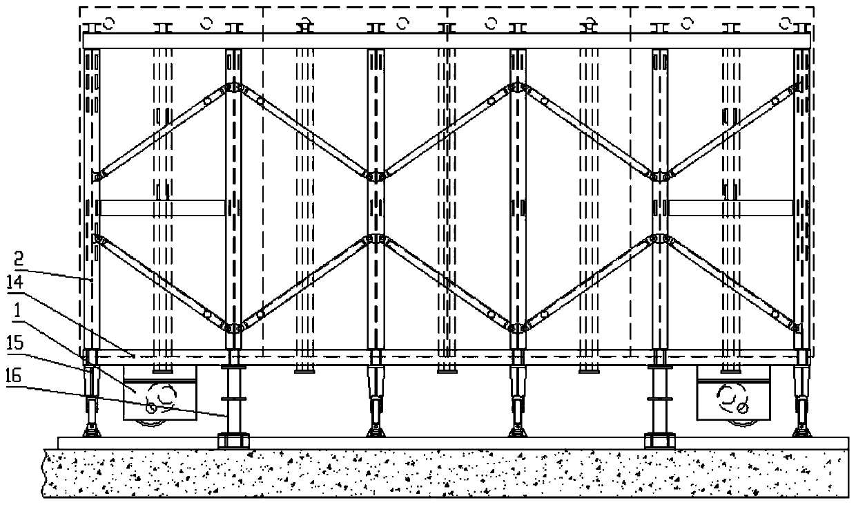
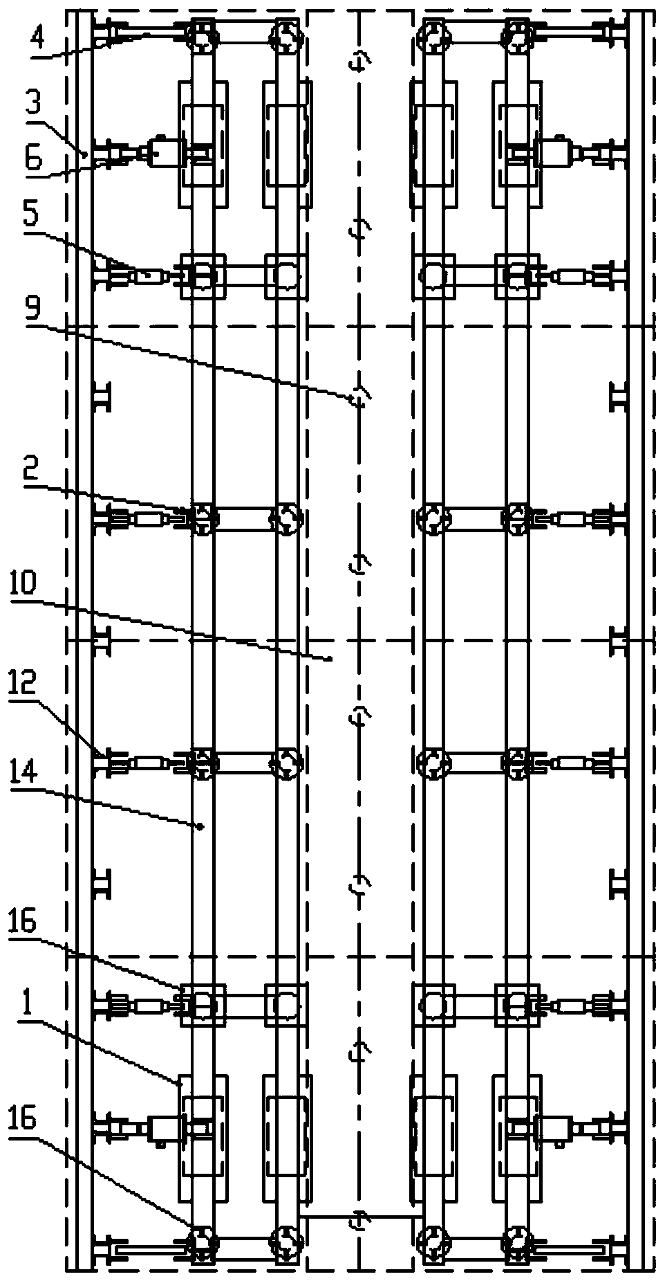
[0041]As shown in the figure, a quick support formwork for a pipe gallery according to the present invention includes a walking structure 1, a supporting structure located on the upper part of the walking, an auxiliary structure for assisting construction, and a side wall formwork 3, a top corner formwork 7, a top Side formwork 8 and top middle formwork 10.

[0042] The walking structure 1 includes a walking frame, a walking motor installed on the walking frame, and a walking wheel driven by the walking motor. The walking wheel is installed under the walking frame, and the walking motor is connected with the walking wheel through a deceleration assembly to drive the walking wheel to rotate. .

[0043] The support structure includes a support base 14, a special-shaped column 2, a positioning connector 4, a support screw 5, a demoulding cylinder 6, a side wall formwork support 12, and a top formwork support 11. Wherein, the bottom of the support base 14 is provided with the wal...

Embodiment 2

[0049] On the basis of Example 1, the construction scheme based on the rapid support formwork for the pipe gallery of Example 1 mainly includes the following steps:

[0050] Step 1: Construct the reinforced skeleton of the side walls of the pipe gallery on the floor of the poured pipe gallery, then lay the walking track on the floor surface, hoist the rapid support formwork in batches, place them on the track, and quickly support the formwork It should be used in combination with two sets;

[0051] Step 2: Assemble the fast support formwork one by one in the order from bottom to top. The specific process of assembly is: place the pre-assembled walking structure 1 and support base 14 on the track, and lift the cylinder 16 through the integral jacking structure of the auxiliary structure. And fix the lead screw 15 in place to form the bottom support, and apply an appropriate counterweight on the upper surface of the support base, then hoist the special-shaped columns 2 one by on...


PUM


Abstract

The invention discloses a quick support formwork for a pipe gallery and a construction method thereof. The quick support formwork includes a traveling structure, a supporting structure located on theupper part of the traveling structure, an auxiliary structure used for assisting construction, a side wall formwork, a top corner formwork, a top side formwork, and a top middle formwork; the supporting structure includes a support base, a special-shaped vertical column, a positioning connector, a support screw, a demolding oil cylinder, a side wall formwork bracket, a top mold bracket, the special-shaped vertical column is mounted on the support base as the main body of the supporting structure, the positioning connector, the support screw, and the demolding oil cylinder are mounted on the outer side of the special-shaped vertical column and connected with the side wall formwork bracket; the auxiliary structure includes an integral jacking cylinder, an in-place fixing screw, a rotating platform, and a middle support rod used for supporting the top middle formwork. When side wall position concrete meets the demolding requirements specified in the construction specifications, the side wall formwork and the top side formwork can be demolded separately, and the top middle formwork is retained until the concrete strength of pipe gallery roof slabs fully meet the design requirements.

Description

technical field [0001] The invention relates to the field of pipe gallery construction equipment, in particular to a quick support formwork for a pipe gallery and a construction method thereof. [0002] technical background [0003] With the rapid development of the economy, the development of pipe corridors for municipal comprehensive facilities has become the mainstream trend of urban construction and renovation. The internal support requires a lot of manpower and material resources, and the labor intensity is high, and the construction efficiency is not ideal. At the same time, due to the many splicing positions of the formwork, the surface quality of the pipe gallery after demoulding is poor. At the same time, a simple formwork trolley is used to carry out the pipe gallery applied to improve construction efficiency. However, for the construction of narrow pipe corridors, due to the limited internal space, simple trolleys cannot be laid smoothly, and the widely used loose...

Claims


Application Information

Patent Timeline
IPC IPC(8): E02D29/045
CPCE02D29/10
Inventor 刘兴波吴相斌李志军哈建波刘伟董志伟李东顺马艳红晋龙凤高子谦陈海建岳琳琳马新磊
Owner 中铁隧道集团二处有限公司
Learn More