Annular inner support system for foundation pit and support replacement construction method

A foundation pit and ring-shaped technology, applied in the direction of foundation structure engineering, excavation, foundation structure test, etc., can solve the problems of cumbersome installation and removal, inability to increase symmetrical force, and inability to monitor symmetrical force, so as to solve the inconvenience of dismantling and prevent The effect of slipping and loosening, fast construction speed

Inactive Publication Date: 2019-12-31
CHINA FIRST METALLURGICAL GROUP
View PDF7 Cites 1 Cited by
  • Summary
  • Abstract
  • Description
  • Claims
  • Application Information

AI Technical Summary

Problems solved by technology

This method has the following defects: 1) The supporting member required for temporary force transmission in the construction stage is permanently discarded in the main structure, and can no longer play its role, increasing material loss, wasting the project cost, and inconvenient to use; 2. ) Due to the characteristics of concrete, there is shrinkage and deformation of the concrete on both sides of the post-cast belt. The existing post-cast belt force-transmitting components cannot monitor the symmetrical force, and cannot increase the symmetrical force in time according to the shrinkage of the post-cast concrete. Moreover, the installation and removal are cumbersome and troublesome.

Method used


Image

  • Annular inner support system for foundation pit and support replacement construction method
  • Annular inner support system for foundation pit and support replacement construction method
  • Annular inner support system for foundation pit and support replacement construction method

Examples


Embodiment Construction

[0031] The present invention will be further described below in conjunction with the accompanying drawings and embodiments.

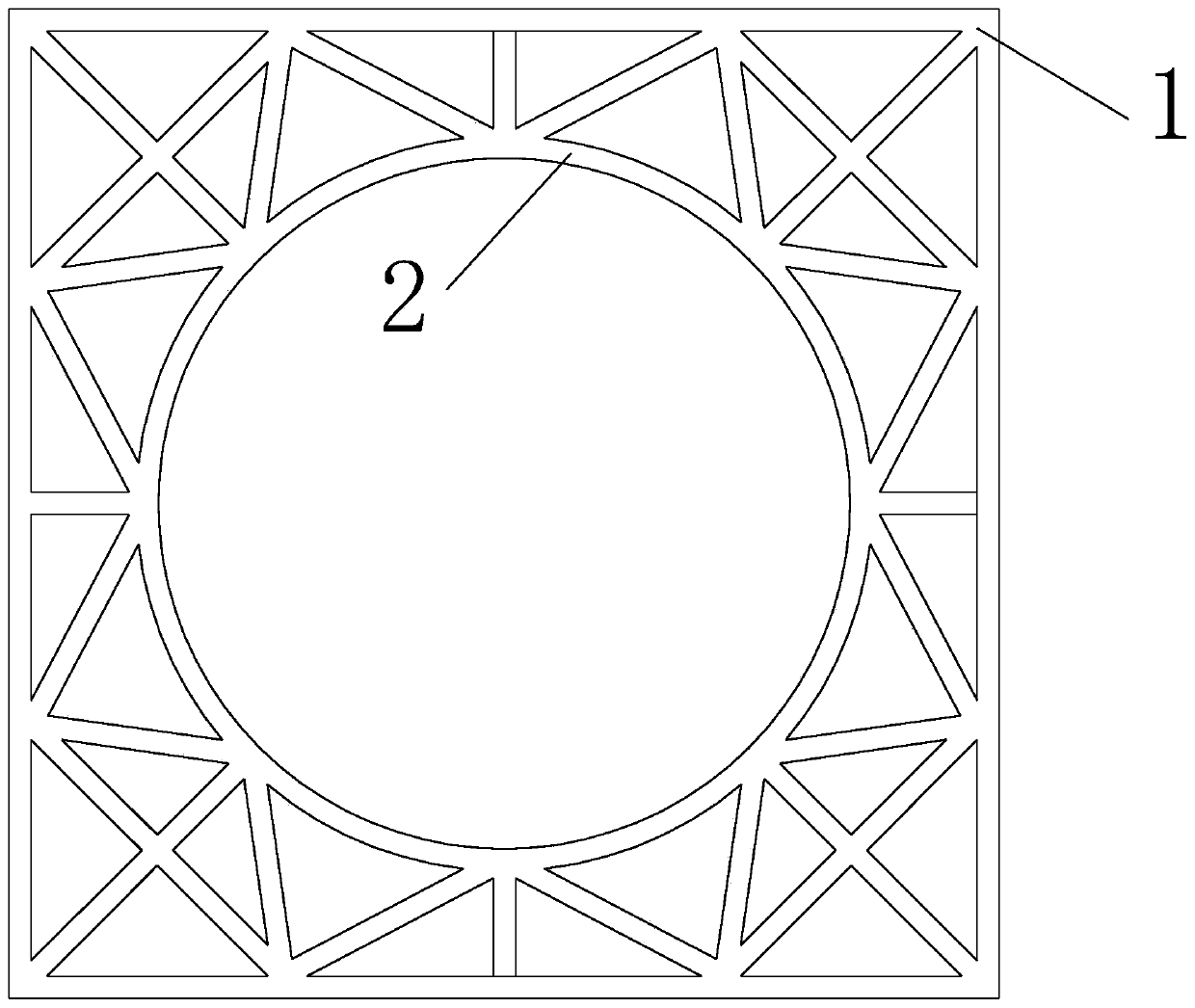
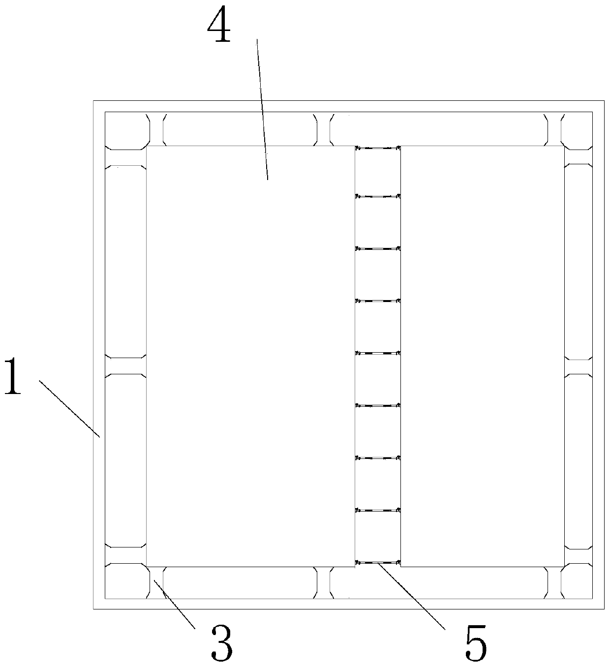
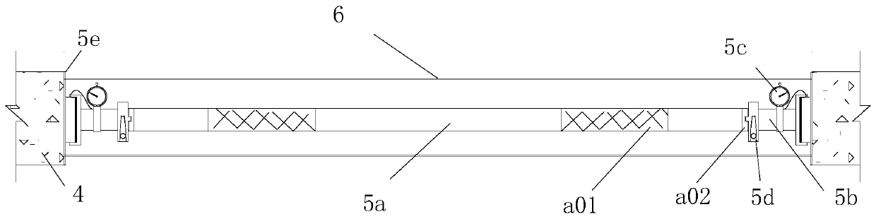
[0032] Such as Figure 1 to Figure 4 As shown, a ring-shaped internal support system of a foundation pit includes a vertical support member 1 arranged along the periphery of the foundation pit and a main structure 4 located in the foundation pit. The inner side of the vertical support member 1 is connected with a circular horizontal structure composed of reinforced concrete beams. The inner support 2, the concrete power transmission belt 3 is distributed between the periphery of the main structure 4 and the vertical support member 1, the main structure 4 is provided with a post-cast belt, and the post-cast belt is equipped with a post-cast steel bar 6 and a post-cast belt The dowel bar 5, the post-casting belt dowel bar 5 includes a main bar 5a and two sets of adjusting bars 5b located at both ends of the main bar 5a, a pressure sensor 5c, a locking mec...


PUM


Abstract

The invention discloses an annular inner support system for a foundation pit and a support replacement construction method. The inner side of a vertical supporting component is connected with an annular horizontal inner support composed of reinforced concrete beams, concrete force-transmitting belts are distributed between the periphery of a main structure and the vertical supporting component, apost-pouring belt is arranged on the main structure and internally provided with post-pouring belt steel bars and post-pouring belt force-transmitting rods, each post-pouring belt force-transmitting rod comprises a main rod and further comprises two sets of adjusting rods, pressure sensors, locking mechanisms and end sealing plates located at the two ends of the main rod correspondingly, one endsof the adjusting rods are in threaded connection with the ends of the main rod, bases are arranged at the other ends of the adjusting rods, and anti-slip pads are placed in the bases; and when the main rod is rotated, the adjusting rods at the two ends can extend simultaneously, the end sealing plates are jacked on the two sides of the post-pouring belt through the anti-slip pads, the locking mechanism can lock the rotation angles of the main rod and the adjusting rods, and the pressure sensors can detect jacking force of the ends where the pressure sensors are located. The construction spaceis large, the construction speed is high, mounting and demounting are convenient, reutilizing can be achieved, and the construction effect is guaranteed.

Description

technical field [0001] The invention belongs to the field of building construction, and in particular relates to a foundation pit annular inner support system and a support replacement construction method. Background technique [0002] For the excavation construction of underground structures in soft soil areas, it is often necessary to take support measures on the side of the foundation pit to ensure that the soil outside the foundation pit does not deform and slip into the foundation pit. When the soil deformation is sensitive, the supporting method of internal support plus cast-in-place piles around the pit or continuous wall is often used. For irregular foundation pits, if the internal support provided by the conventional counter-bracing method is used, the excavation space of the foundation pit will be reduced, resulting in inconvenient excavation and complex structures. The force characteristics are not easy to be determined, so it is necessary to carry out support re...

Claims


Application Information

Patent Timeline
IPC IPC(8): E02D17/04E02D33/00
CPCE02D17/04E02D33/00E02D2600/10
Inventor 刘奎余珊郑涛孙仕斌刘明周廖红玉孙广宏黄达锴
Owner CHINA FIRST METALLURGICAL GROUP
Why Eureka
Try Eureka