
Combined box-type subgrade without bottom plate and subgrade construction method

A baseless, combined technology, applied in roads, roads, buildings, etc., can solve the problems of high construction costs and long construction time of railway subgrade engineering

Inactive Publication Date: 2019-12-31
周兆弟
View PDF0 Cites 3 Cited by
  • Summary
  • Abstract
  • Description
  • Claims
  • Application Information

AI Technical Summary

Problems solved by technology

However, the width of this trapezoidal railway subgrade structure is several times the width of the subgrade surface, and it needs to occupy more land resources such as cultivated land and forest land. Due to the lack of qualified fillers in plain areas, the fillers need to be transported over long distances, and the foundation soil The layer is generally deep and soft, and foundation treatment is required, resulting in a longer construction time and higher construction costs for railway embankment projects

Method used


Image

  • Combined box-type subgrade without bottom plate and subgrade construction method
  • Combined box-type subgrade without bottom plate and subgrade construction method
  • Combined box-type subgrade without bottom plate and subgrade construction method

Examples


Embodiment 1

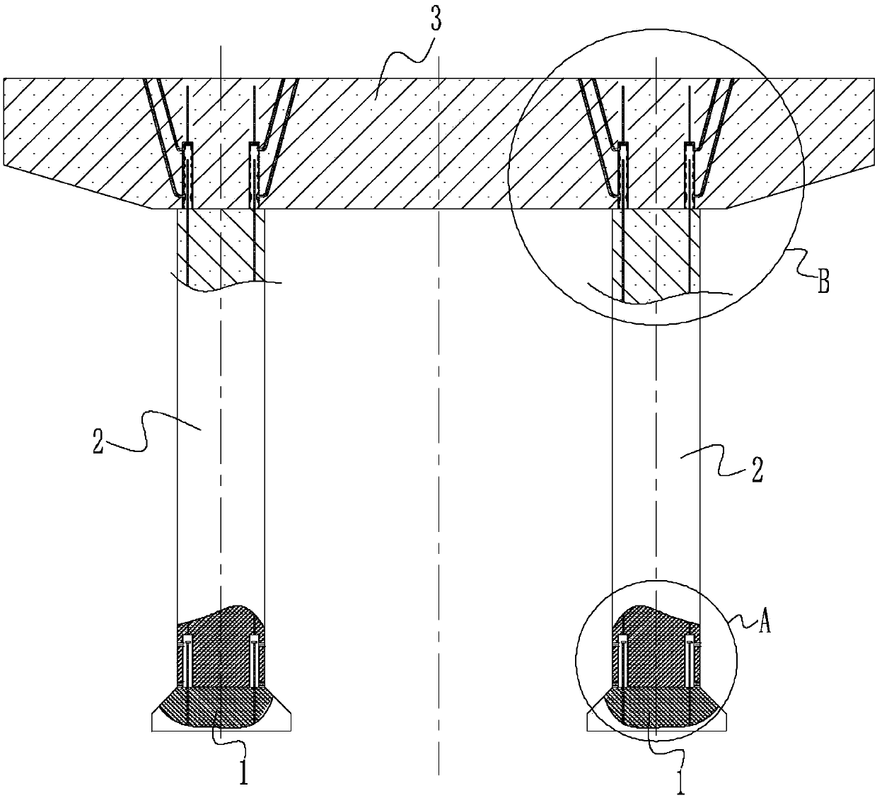
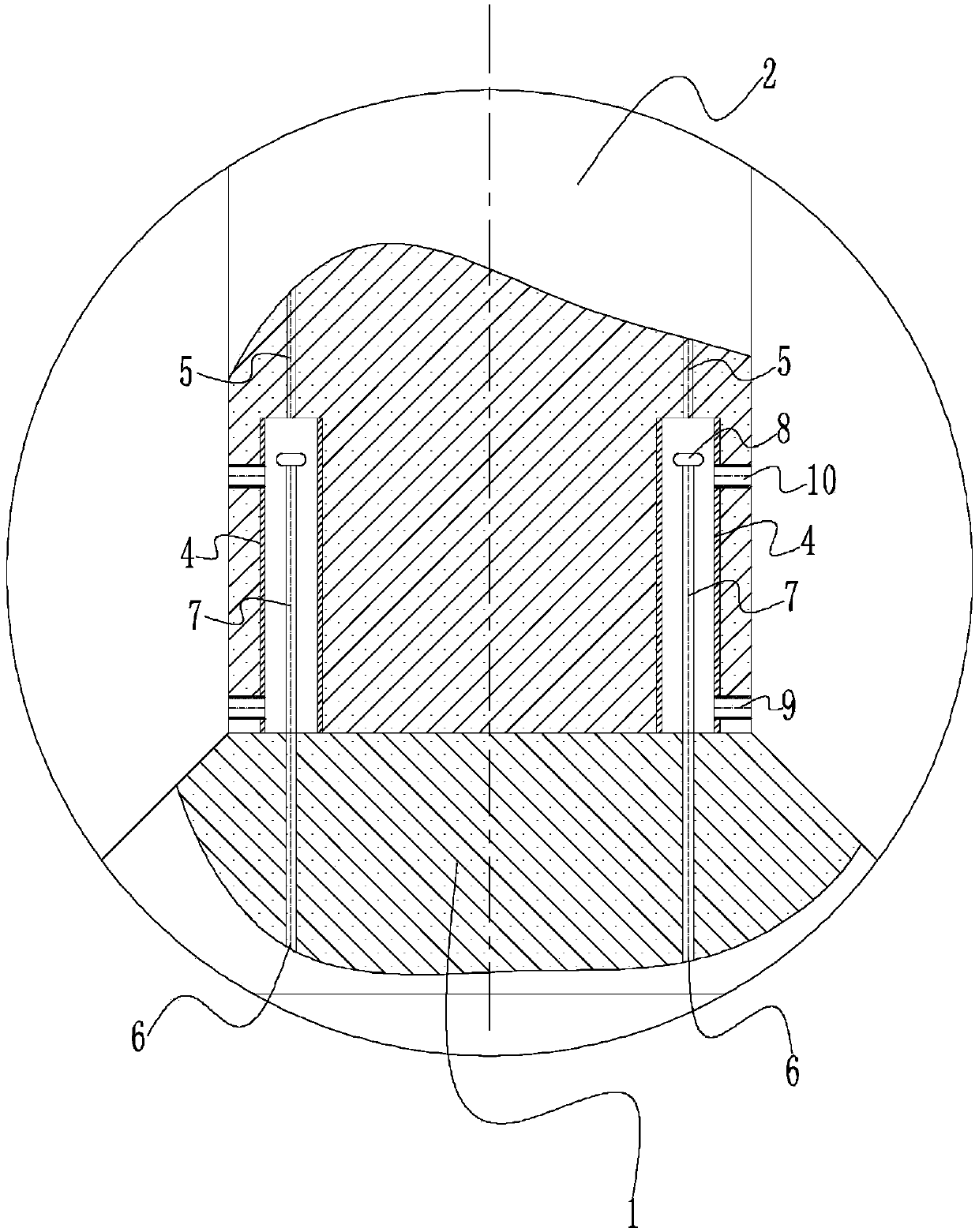
[0063] like Figure 1 to Figure 3 As shown, the combined bottomless box-type roadbed provided in this embodiment includes two caps 1, two lateral walls 2 and a roof 3, wherein the roof 3 is a prefabricated concrete slab, and the lateral wall 2 is a prefabricated concrete wall , the two lateral walls 2 are parallel to each other, the top plate 3 is located above the platform 1, and the vertical ends of each lateral wall 2 are respectively spliced ​​with a platform 1 and the top plate 3 to form a hollow box without a bottom plate. Both sides of the bottom of the lateral wall 2 are vertically embedded with a plurality of connecting sleeves 4 with open lower ends, each connecting sleeve 4 is arranged in two rows along the length direction of the lateral wall 2, and the connecting sleeves 4 The upper end is welded or screwed to the first vertical main reinforcement 5 pre-embedded on both sides of the lateral wall 2, and the cap 1 is embedded with the second vertical main reinforcem...

Embodiment 2

[0068] like Figure 4 to Figure 6 As shown, in the combined bottomless box-type subgrade provided by this embodiment, a plurality of connecting sleeves 4 with open lower ends are vertically buried on both sides of the bottom of the lateral wall 2, and each connecting sleeve 4 is arranged along the lateral wall 2. The length direction is arranged in two rows, and the upper end of the connecting sleeve 4 is welded or screwed to the first vertical main ribs 5 embedded on both sides of the lateral wall 2, and the cap 1 is embedded with the first Two vertical main ribs 6 , when the lateral wall 2 is spliced ​​with the platform 1 , the connecting sleeve 4 axially fits the end 7 of the second vertical main rib 6 . The inner cylinder wall of the connecting sleeve 4 is formed with a concave-convex surface. The lower end of the tube wall connecting the sleeve 4 is provided with a slurry inlet, and the wall surface of the lateral wall 2 and the slurry inlet are connected by a slurry inl...

Embodiment 3

[0073] like Figure 7 As shown, the structure of the cap platform 1 and the lateral wall 2 of the combined bottomless box-type subgrade provided in this embodiment and the connection method of the two are the same as those in Embodiment 1, and will not be repeated here.

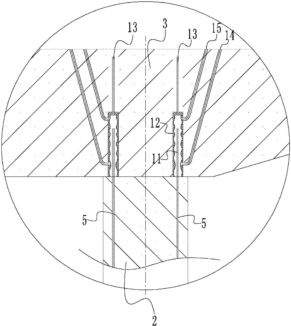
[0074] The top plate 3 is overlapped with the lateral wall 2, and the middle part of the lateral wall 2 is buried with the first vertical main rib 5 exposed at the top 11, and the corresponding position of the top plate 3 and the first vertical main rib 5 is provided with a through cast-in-place hole 16 , when the top plate 3 is overlapped with the lateral wall 2, the top 11 of the first vertical main rib 5 of the lateral wall 2 is inserted into the cast-in-place hole 16 of the roof 3, and the inner cavity of the cast-in-place hole 16 is a concave-convex surface. A portion of the top 11 of a vertical main rib 5 is bent into an L shape, and the top 11 of the first vertical main rib 5 of the lateral wall 2 is f...


PUM


Abstract

The invention discloses a combined box-type subgrade without a bottom plate. The combined box-type subgrade comprises two bearing platforms, two lateral walls and a top plate, the top plate is a prefabricated concrete plate, and the lateral walls are prefabricated concrete walls; the two lateral walls are parallel to each other, the top plate is located on the bearing platforms, and the two vertical ends of both of the lateral walls are spliced with the two bearing platforms and the top plate correspondingly to form a hollow box body without the bottom plate. The invention further discloses asubgrade construction method. The subgrade construction method comprises the following steps: a foundation is treated, specifically, pipe piles or cast-in-situ bored piles are arranged in the foundation; the subgrade is laid, specifically, a first section of the subgrade is laid firstly, the concrete bearing platforms are poured on the foundation or the prefabricated bearing platforms are laid onthe foundation, the pile ends of the pipe piles or the pile ends of the cast-in-situ bored piles are anchored into the bottoms of the bearing platforms, then the lateral walls are connected with the bearing platforms, and then the top plate is fixed; and the subgrade laying step is repeated to lay other sections of the subgrade sequentially until laying is completed. According to the combined box-type subgrade without the bottom plate, land resources can be saved, the construction time of railway subgrade engineering can be shortened, and the construction cost of the railway subgrade engineering can be reduced.

Description

technical field [0001] The invention relates to a combined bottomless box-type roadbed and a roadbed construction method, belonging to the technical field of civil engineering. Background technique [0002] The current railway subgrade structure usually adopts a trapezoidal type, which is composed of the surface layer of the subgrade bed, the bottom layer of the subgrade bed and the subgrade body, and different standards of fillers are used in different parts for layered rolling treatment. The two sides of the subgrade structure are usually 1:1.5-1: The filling slope rate of 2 is sloped to the ground. This kind of railway subgrade structure has the advantages of safety and high operating comfort, and is currently the most widely used subgrade structure type at home and abroad. However, the width of this trapezoidal railway subgrade structure is several times the width of the subgrade surface, and it needs to occupy more land resources such as cultivated land and forest land...

Claims


Application Information

Patent Timeline
IPC IPC(8): E01C3/00
CPCE01C3/00
Inventor 周兆弟
Owner 周兆弟
Learn More