
Fur stretching device

A stretching device and fur technology, which is applied to leather stretch/stretching, raw hide/leather/fur manufacturing equipment, small raw hide/large raw hide/leather/fur processing, etc., can solve the problem of poor tensioning effect and inconvenience Small-scale adjustment, easy sliding of the plug-in block, etc., to achieve the effect of easy implementation, stability, and simple operation

Active Publication Date: 2019-12-31
北京束兰国际服装有限责任公司
View PDF7 Cites 6 Cited by
  • Summary
  • Abstract
  • Description
  • Claims
  • Application Information

AI Technical Summary

Problems solved by technology

[0004] The above-mentioned fur stretching composite plate structure is used to change the distance between the fur nail plates by embedding plug-in blocks between the fur nail plates, so as to stretch the fur. The fur stretch structure is relatively simple, but When the fur is stretched, the distance is only adjusted by the plug-in block. With the insertion of the plug-in block, the fur is constantly tensioned. The greater the resistance of the plug-in block, the more difficult it is to insert the plug-in block. Therefore In the process of inserting the plug-in block, it is necessary to smash it in with tools such as a hammer, and when stretching the fur, it is necessary to pay great attention to the tension of the fur. It is inconvenient to make small-scale adjustments by smashing the plug-in block with a hammer; After positioning, it takes a period of time to keep the fur in a stretched state. In the middle, the fur stretch structure needs to be transferred, and the fur top plate is only limited by the plug-in block. The plug-in block is easy to slide, making the The pegboard of the fur is close, the fur becomes loose, and the tensioning effect is not good

Method used


Image

  • Fur stretching device
  • Fur stretching device

Examples


Embodiment

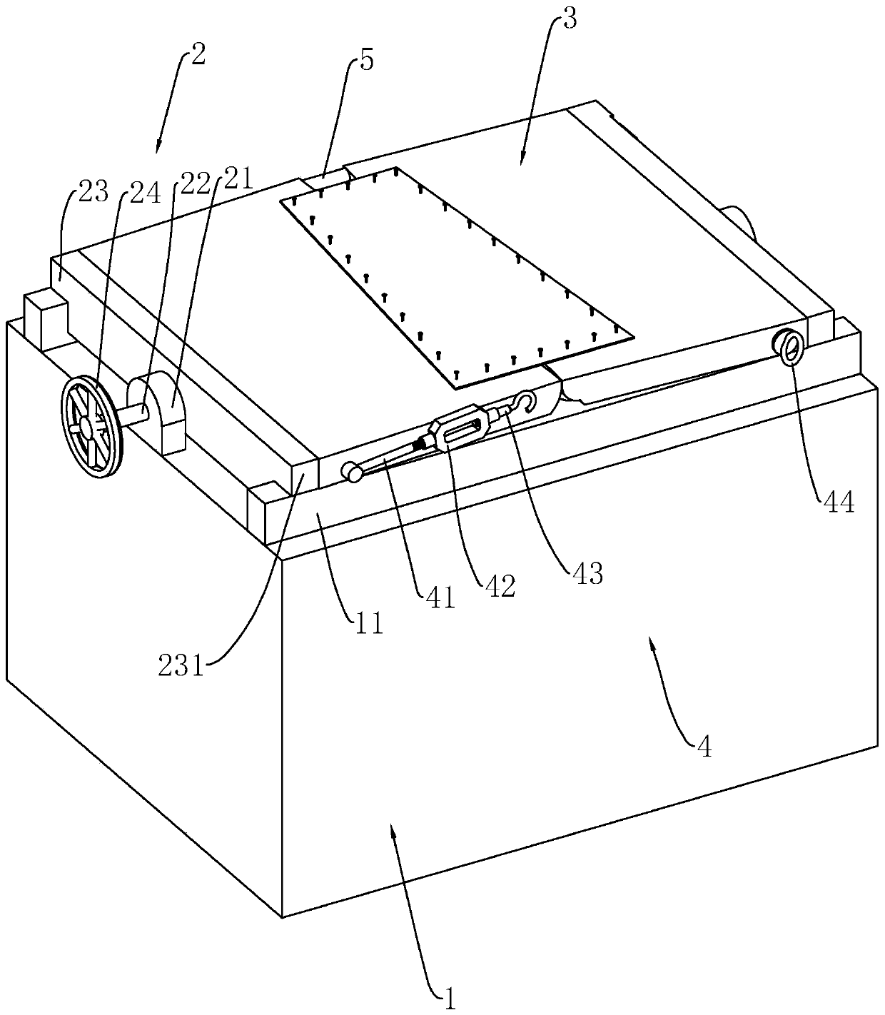
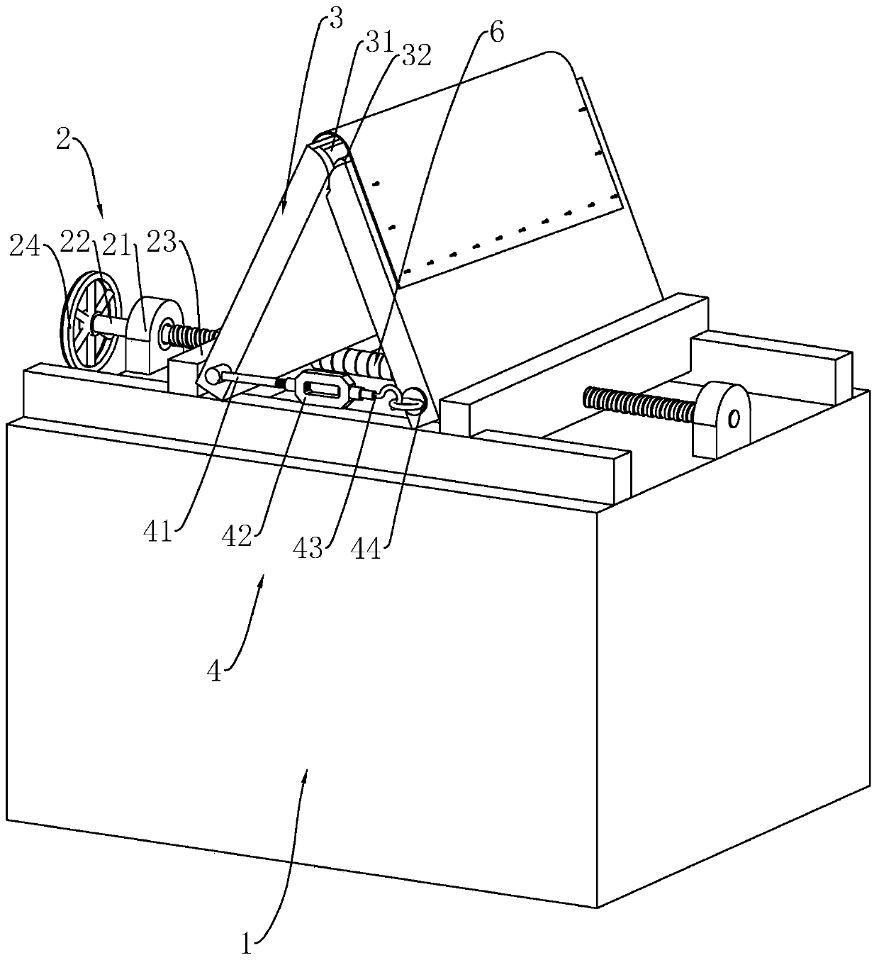
[0030] refer to figure 1 , a fur stretching device, comprising a supporting platform 1, a clamping assembly 2, a nail plate 3, and a positioning member 4; the supporting platform 1 is arranged on the ground; the clamping assembly 2 is arranged on the upper surface of the supporting platform 1, and clamped The assembly 2 includes a fixed end seat 21, a screw rod 22, and a clamping block 23; there are two fixed end seats 21, which are arranged on the upper surface of the support table 1, and are located at both ends of the upper surface of the support table 1; the screw rod 22 is rotated to set Between the two fixed end seats 21, and one end of the screw rod 22 extends through one of the fixed end seats 21, the screw rod 22 is provided with two sections of threads with opposite directions of rotation (refer to figure 2); there are two clamping blocks 23, a threaded through hole is provided in the middle of the clamping block 23, the screw mandrel 22 cooperates with the threaded...


PUM


Abstract

The invention relates to a fur stretching device. The fur stretching device comprises a supporting table, a clamping assembly, nail plates and a positioning piece, the supporting table is placed on the ground, two sliding rails are arranged on the two sides of the upper surface of the supporting table, the clamping assembly is arranged on the supporting table and located between the two sliding rails, the clamping assembly comprises clamping blocks, the clamping blocks are in sliding connection with the sliding rails, the two nail plates are provided and are horizontally placed on the slidingrails, fur is fixed on the nail plates, the side surfaces of the sides, close to each other, of the nail plates are arranged as arc surfaces, the clamping blocks can push the two nail plates to move towards each other, so that the connecting portion of the nail plates is arched upwards to stretch the fur, the two nail plates form a V-shaped structure, an opening faces downwards, the positioning piece is arranged at the opening of the V-shaped structure formed by the two nail plates, and the positioning piece connects the lower ends of the two nail plates to define the positions of the two nailplates. According to the fur stretching device, the fur can be stretched, moreover, the fur can be kept in a stable tension state in a relatively long period of time, and the problem of looseness isnot prone to occurrence.

Description

technical field [0001] The invention relates to fur processing equipment, in particular to a fur stretching device. Background technique [0002] The fur stretching device is a kind of equipment used in the fur processing process. The unprocessed fur is wrinkled and uneven. Such fur is not conducive to subsequent processing. The fur stretching device is used to stretch and stretch the unprocessed fur , making it smooth and easy to process. [0003] In the patent document whose authorized notification number is CN206553539U, a fur stretch composite board structure is disclosed, which comprises at least two fur nail boards, two fur nail boards and two fur nail boards Inserting rods with a sliding fit, used for fixing the fur on the two fur nail plates, and inserting between the two fur top plates to realize the insertion of the two fur top plates away from each other along the axis of the insert rod block; when in use, pass the insertion rod through the two fur nail plates, ...

Claims


Application Information

Patent Timeline
IPC IPC(8): C14B1/26C14B17/08
CPCC14B1/26C14B17/08
Inventor 杨旗杨时光
Owner 北京束兰国际服装有限责任公司
Learn More