
Fixed angle feeding mechanical arm mechanism

A fixed-angle, manipulator technology, applied in the direction of conveyor objects, transportation and packaging, etc.

Pending Publication Date: 2019-12-31
苏州竹日精密机械有限公司
View PDF0 Cites 2 Cited by
  • Summary
  • Abstract
  • Description
  • Claims
  • Application Information

AI Technical Summary

Problems solved by technology

[0004] In order to solve the above technical problems, the purpose of the present invention is to provide a fixed-angle feeding manipulator with a compact structure, stable operation, reduced personnel costs and waste of downtime, and can meet the needs of large-scale industrial production

Method used


Image

  • Fixed angle feeding mechanical arm mechanism
  • Fixed angle feeding mechanical arm mechanism

Examples


Embodiment Construction

[0016] The specific implementation manners of the present invention will be further described in detail below in conjunction with the accompanying drawings and embodiments. The following examples are used to illustrate the present invention, but are not intended to limit the scope of the present invention.

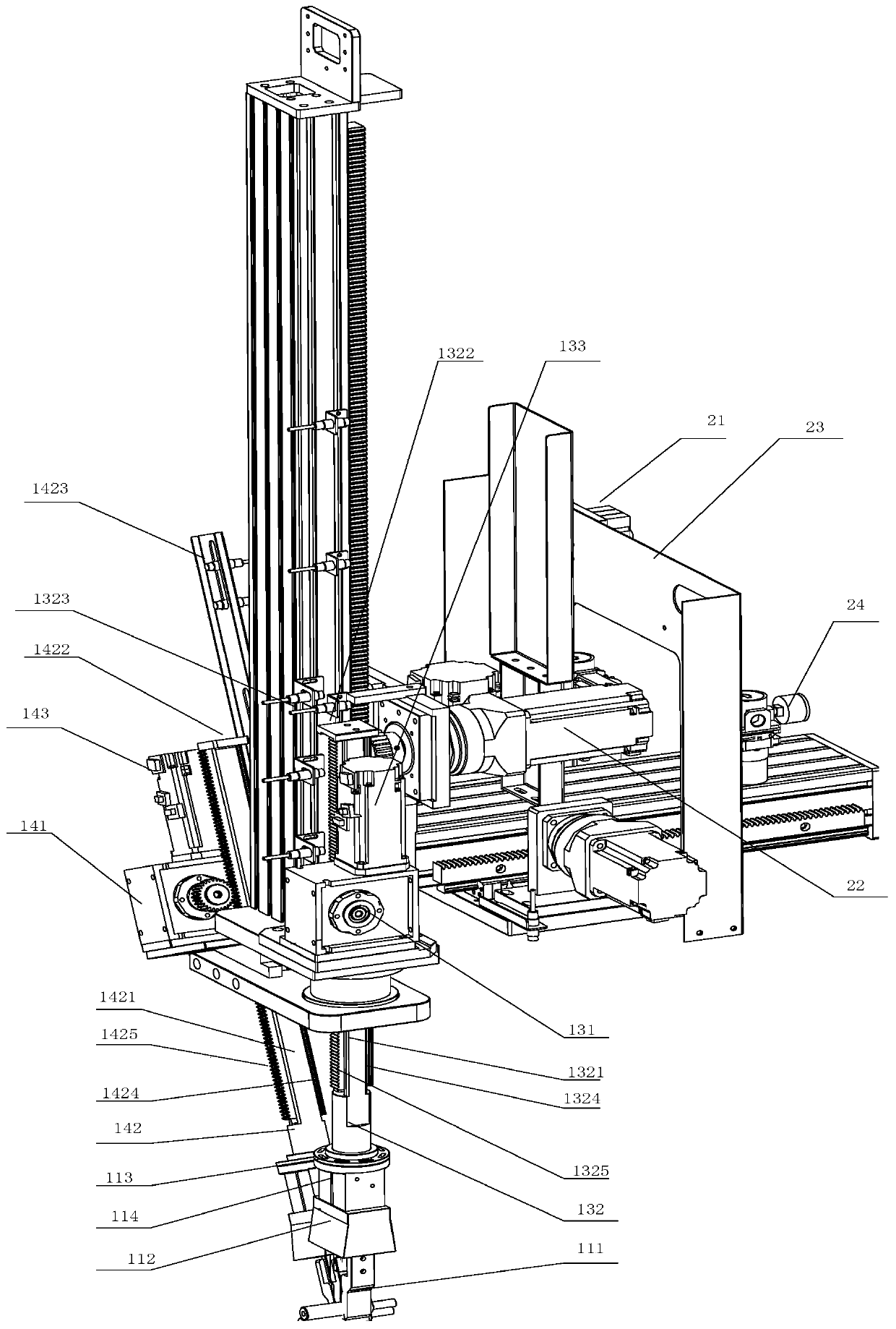
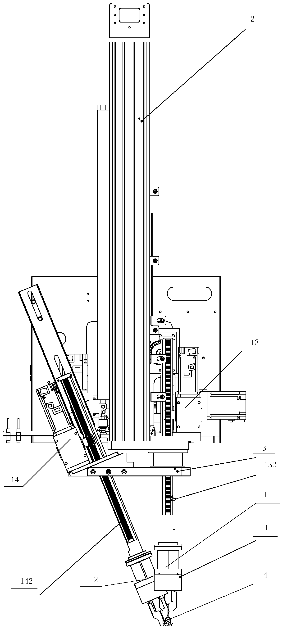
[0017] figure 1 and figure 2 A fixed-angle feeding manipulator mechanism is shown, including a manipulator mechanism 1 fixed on a frame 3 and an integral drive mechanism 2 for driving the manipulator mechanism 1 and the frame 3 to move in the direction of the XYZ axis. 1 includes jaw cylinder assembly 11, jaw cylinder assembly 2 12, and a vertical movement assembly 13 that drives jaw cylinder assembly 11 to move up and down in the Z-axis direction and drives jaw cylinder assembly 2 12 in the XZ axis plane The oblique moving assembly 14 of oblique movement, the up and down moving assembly 13 comprises a transmission mechanism one 131, a linkage mechanism one 132 and a fi...


PUM


Abstract

The invention relates to a fixed angle feeding mechanical arm mechanism, which includes a mechanical arm mechanism fixed on a rack, and an entire driving mechanism for diving the mechanical arm mechanism and the rack to do bulk movement in the X,Y and Z axis directions; the mechanical arm mechanism includes a clamping jaw air cylinder component I, a clamping jaw air cylinder component II, as wellas a vertical movement component for driving the clamping jaw air cylinder component I to do vertical movement in the Z axis direction respectively, and a slant movement component for driving the clamping jaw air cylinder component II to do slant movement in the X and Z axial plane. The fixed angle feeding mechanical arm mechanism provided by the invention is compact in structure, can be used forclamping a machined eccentric shaft in a main shaft chuck from main equipment and conveying blank not machined to the main shaft chuck through the design of the clamping jaws in two directions, thereby reducing wait time of halt caused by manual blank taking and feeding of staff, and being rather high in automation degree.

Description

technical field [0001] The invention relates to a manipulator device, in particular to a fixed-angle feeding manipulator mechanism. Background technique [0002] The inherent eccentric shaft design of the existing parts makes many manipulators unable to meet the processing requirements. The main equipment is arranged in an assembly line, and robots cannot be installed. Based on the above defects, the present invention relates to a fixed-angle feeding manipulator mechanism, which can solve these disadvantages and enable better automation on site. [0003] In view of the above problems, the main technical problem to be solved by the present invention is to provide a fixed-angle feeding manipulator mechanism with compact structure, high degree of automation, better automation on site, stable operation, and meeting different processing beats and quality requirements. . Contents of the invention [0004] In order to solve the above technical problems, the object of the presen...

Claims


Application Information

Patent Timeline
Patent Type & Authority Applications(China)
IPC IPC(8): B65G47/91
CPCB65G47/912
Inventor 顾东卫郝敬楠章佳发
Owner 苏州竹日精密机械有限公司
Learn More