
A long-axis gear precision forming device with a boss

A precision forming and long axis technology, applied in forging/pressing/hammer devices, forging/pressing/hammering machinery, manufacturing tools, etc., can solve the problems of easy failure of parts, discount of mechanical properties of parts, metal waste, etc., to achieve Improve material utilization, reduce machining costs, and save metal materials

Active Publication Date: 2021-01-22
ZHENGZHOU RES INST OF MECHANICAL ENG CO LTD
View PDF7 Cites 0 Cited by
  • Summary
  • Abstract
  • Description
  • Claims
  • Application Information

AI Technical Summary

Problems solved by technology

[0002] Long shaft gears with bosses are mostly used in transmissions of heavy and medium-sized trucks and buses. They are important parts for transmitting torque in the transmission. The rigidity and strength of this part have a great influence on the transmission performance. If the mechanical properties of the parts are not up to standard, broken shafts or broken teeth will cause serious safety accidents
The current commonly used processing method for this part is to design it as a split structure. The long axis part with the boss and the part with the spoke sprocket are forged separately, and welded for use after machining. The parts manufactured by this method are welded parts prone to failure
If the part is forged as a whole structure, since there is a boss at the long axis, and a disc tooth with spokes is set at one end of the long axis, generally speaking, the common open die forging method and closed upsetting extrusion method are used. It is difficult to form the bosses and spokes on the long axis at the same time, because this structure makes it difficult for the forging to be released from the mold. Now it is only possible to forge the rough shape and then rely on mechanical turning to form the bosses and spokes of the long axis. Such processing This method cannot retain a reasonable forging streamline, because the forging streamline is cut off by mechanical turning, the mechanical properties of the parts are also greatly reduced, and the metal waste is also very serious

Method used


Image

  • A long-axis gear precision forming device with a boss
  • A long-axis gear precision forming device with a boss
  • A long-axis gear precision forming device with a boss

Examples


Embodiment Construction

[0025] In order to make the purpose, technical solutions and advantages of the embodiments of the present invention clearer, the technical solutions in the embodiments of the present invention will be clearly and completely described below in conjunction with the accompanying drawings in the present invention. Obviously, the described embodiments are the Some embodiments of the invention are not all embodiments. Based on the embodiments of the present invention, all other embodiments obtained by those of ordinary skill in the art without creative efforts fall within the protection scope of the present invention.

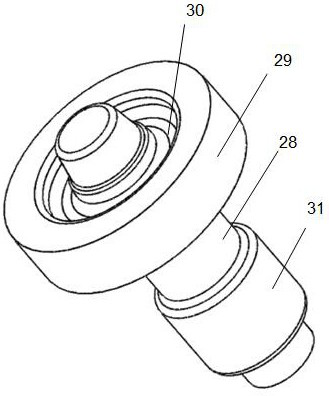
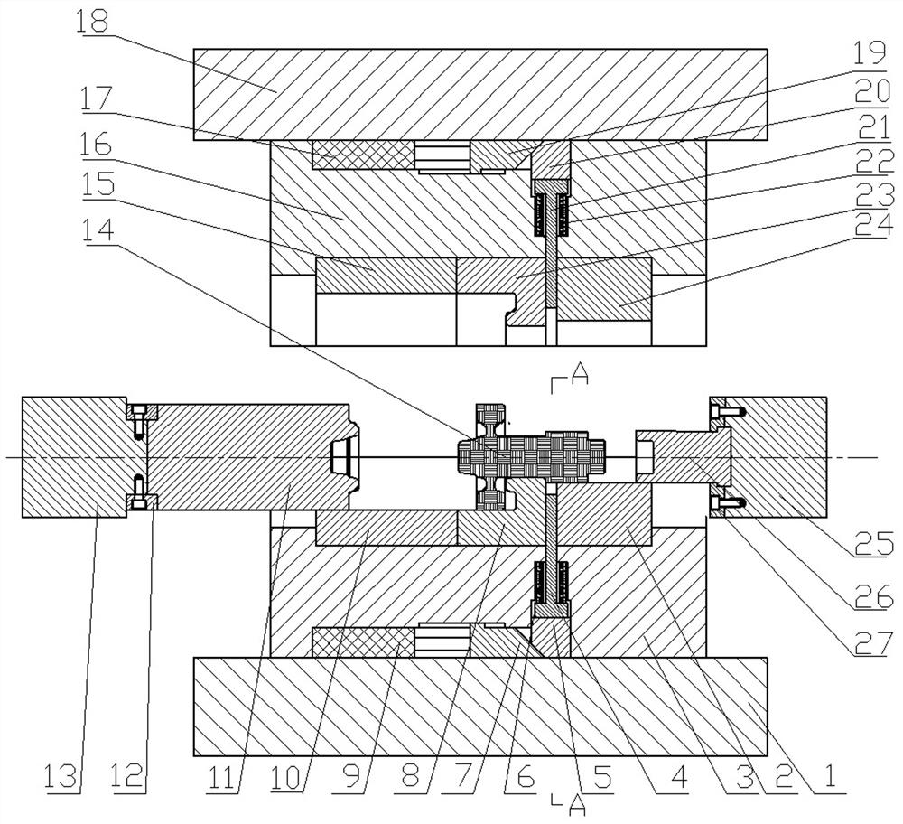
[0026] Such as figure 1 As shown, the long-axis gear produced by the present invention includes a long shaft 28, a disc tooth 29 arranged at one end of the long shaft and having a spoke 30, and a boss 31 arranged at the other end of the long shaft. The horizontally placed stock bar 14 is forged to form the long shaft gear.

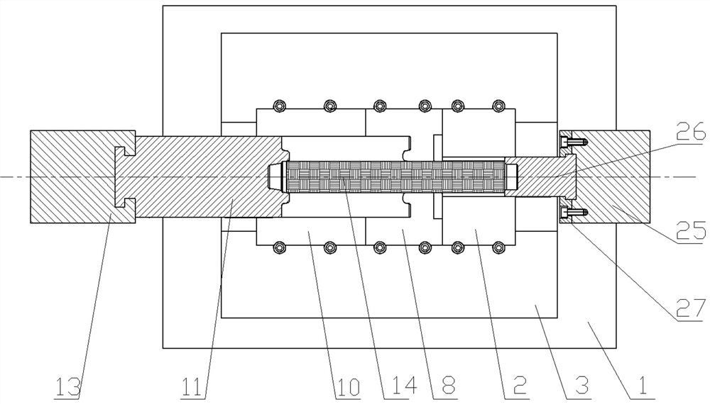
[0027] Such as figure 2 and image 3 A...


PUM


Abstract

The invention provides a long-axis gear precision forming device with a boss, the precision forming device includes an upper closed die assembly, a lower closed die assembly, a left extrusion die assembly, a right Extrusion die assembly; the present invention can realize single-pass hot forging integrally forming long-axis gear forging billets with bosses, and can form the spokes and long-axis bosses at the same time. Disadvantages of split forming or multi-pass forming; the device can form the spoke part, retain a reasonable distribution of forging streamlines, can effectively improve the mechanical properties of the part, and at the same time realize the flash-free forging of the part, which can Save metal materials, improve material utilization, and at the same time, the machining allowance of forging products is small, reducing the cost of subsequent machining.

Description

technical field [0001] The invention belongs to the technical field of pressure processing of metal parts, and in particular relates to a long-axis gear precision forming device with a boss. Background technique [0002] Long shaft gears with bosses are mostly used in transmissions of heavy and medium-sized trucks and buses. They are important parts for transmitting torque in the transmission. The rigidity and strength of this part have a great influence on the transmission performance. If the mechanical properties of the parts are not up to standard, broken shafts or broken teeth will cause serious safety accidents. The current commonly used processing method for this part is to design it as a split structure. The long axis part with the boss and the part with the spoke sprocket are forged separately, and welded for use after machining. The parts manufactured by this method are welded parts are prone to failure. If the part is forged as a whole structure, since there is a...

Claims


Application Information

Patent Timeline
Patent Type & Authority Patents(China)
IPC IPC(8): B21J13/02
CPCB21J13/02
Inventor 王涛刘华刘百宣刘光辉张义帅
Owner ZHENGZHOU RES INST OF MECHANICAL ENG CO LTD
Learn More