
A urethral drug delivery device

A technology of drug delivery device and urethra, which is applied in the field of medical equipment, can solve the problems of liquid medicine pollution, unfavorable recovery, waste of liquid medicine, etc., and achieve the effect of convenient maintenance in the later stage, increasing the speed of spraying medicine, and reducing the residue of liquid medicine

Active Publication Date: 2021-06-08
FIRST HOSPITAL OF SHANXI MEDICAL UNIV
View PDF8 Cites 0 Cited by
  • Summary
  • Abstract
  • Description
  • Claims
  • Application Information

AI Technical Summary

Problems solved by technology

[0003] At present, for the method of applying medicine to the affected area, most of them are treated with irrigators or urethral drug delivery devices, but in the actual operation process, it is found that the patient feels a strong sense of discomfort, and the existing products usually use one drug delivery port, and the uniformity of drug delivery is poor. , the effect is not good, and there will be some reflux phenomenon, which will cause the liquid medicine in the device to be polluted and affect the therapeutic effect
Although some applicators capable of suppressing reflux are also disclosed in the prior art, for example, Chinese patent CN2016100201546 discloses a urethral applicator for urology, which adopts an injection method of drug delivery, although a reflux applicator is provided. structure, but because the injection tube is long, it is not designed integrally with the sleeve, and the moving distance of the piston is limited, resulting in more liquid medicine remaining in the injection tube after the application is completed, which is not conducive to recycling, resulting in waste of liquid medicine

Method used


Image

  • A urethral drug delivery device
  • A urethral drug delivery device
  • A urethral drug delivery device

Examples


Embodiment Construction

[0025] In order to make the technical means, creative features, goals and effects achieved by the present invention easy to understand, the present invention will be further described below in conjunction with specific embodiments.

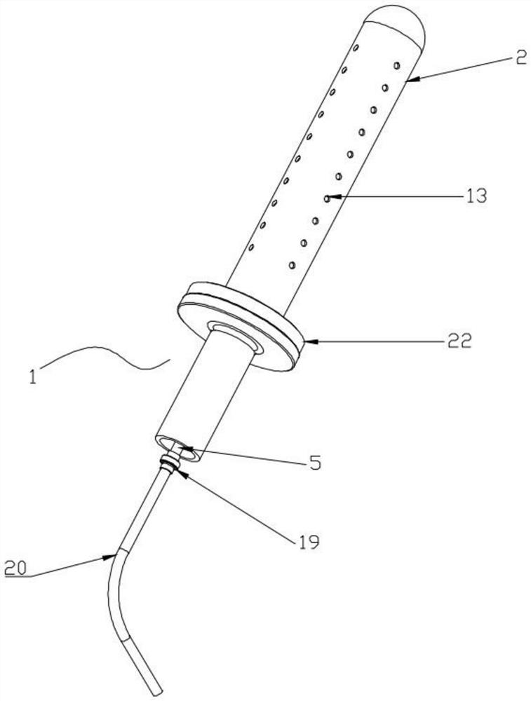
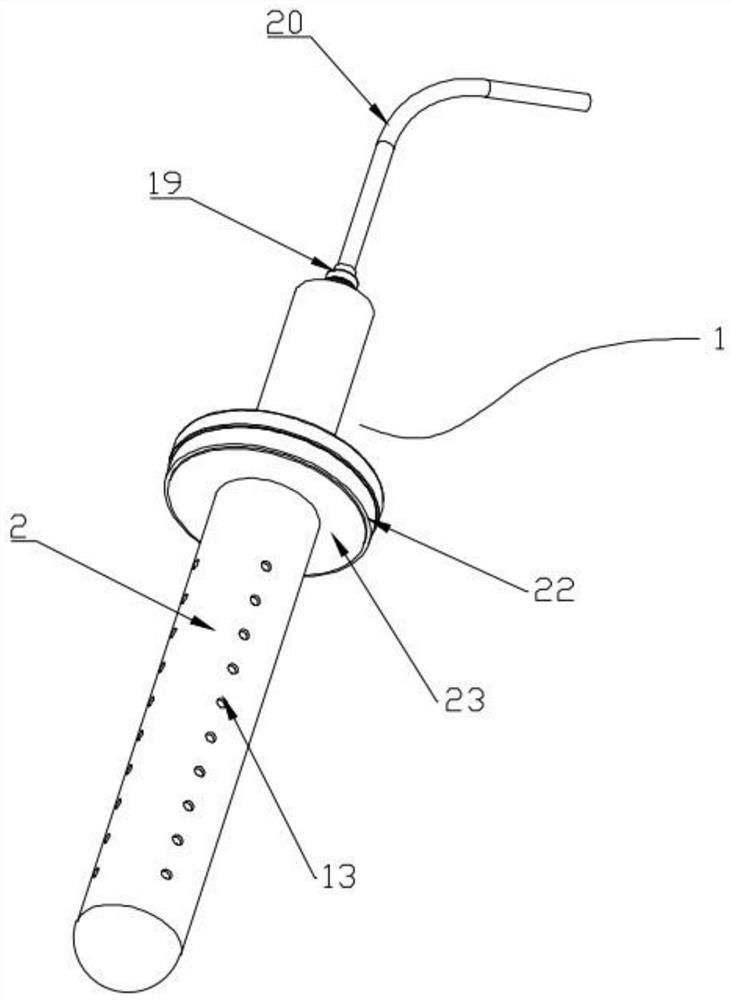
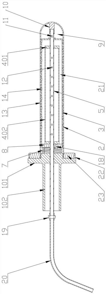
[0026] like Figure 1 to Figure 7 As shown, a urethral drug delivery device includes a grip part 1, an outer sleeve 2, an inner sleeve 3, an expansion part 4 and an air intake tube 5, and one end of the grip part 1 is connected to one end of the outer sleeve 2 Fixed, the inner sleeve 3 is slidably connected in the outer sleeve 2 and a position-limiting mechanism 6 that restricts the movement of the inner sleeve 3 along the length direction of the outer sleeve 2 is also provided between the two, and the inner sleeve 3 There is a return spring 7 sleeved between the handle 1 and a pressurized chamber 9 between the inner end of the inner sleeve 3 and the outer sleeve 2, and the air inlet pipe 5 runs through the handle 1 and the inner sleeve 3 And its...


PUM


Abstract

The invention discloses a urethral drug delivery device, which relates to the field of medical appliances, and comprises a gripping part, an outer sleeve, an inner sleeve, an expansion part and an air intake pipe, and a gap is left between the inner end of the inner sleeve and the outer sleeve. The pressure chamber, the expansion part is fixed on the intake pipe and is located in the inner sleeve, a liquid storage chamber is formed between the expansion part and the inner sleeve, and a number of drain holes are provided on the side wall of the outer sleeve. The cylinder is provided with a liquid discharge hole 2 that cooperates with the liquid discharge hole 1. When the air is ventilated into the intake pipe, the expansion part expands and squeezes the liquid medicine in the liquid storage chamber. At the same time, the inner sleeve Under the action of air pressure in the pressurized chamber, it can move towards the gripping part until the first liquid discharge hole is aligned with the second liquid discharge hole to realize the application of medicine to the affected area. It will cause discomfort to the patient, can isolate the liquid storage chamber from the outside, prevent the reflux of the medicinal liquid or other liquids outside the outer sleeve, will not pollute the medicinal liquid, and has high safety.

Description

technical field [0001] The invention belongs to the field of medical appliances, in particular to a urethral drug delivery device. Background technique [0002] When diagnosing and treating patients (especially women) with diseases such as urinary tract infection or urinary system inflammation, two methods are generally used: 1. Oral medication; 2. Direct medication to the affected area. Because the patient directly acts on the affected part with the drug, the treatment speed is relatively fast. [0003] At present, for the method of administering medicine to the affected area, most of them are treated with irrigators or urethral drug delivery devices, but in the actual operation process, it is found that the patient feels a strong sense of discomfort, and the existing products usually use one drug delivery port, and the uniformity of drug delivery is poor. , the effect is not good, and there will be some reflux phenomenon, which will cause the liquid medicine in the device...

Claims


Application Information

Patent Timeline
Patent Type & Authority Patents(China)
IPC IPC(8): A61M31/00
CPCA61M31/00
Inventor 郝海峰秦延
Owner FIRST HOSPITAL OF SHANXI MEDICAL UNIV
Learn More