
Method and device for automatic detection and defect identification of power grid clamps

An automatic detection and defect recognition technology, applied in measurement devices, optical testing flaws/defects, character and pattern recognition, etc., can solve the problems affecting work efficiency, slow model training, long model update cycle, etc., to improve detection and recognition efficiency. Effect

Inactive Publication Date: 2019-12-27
ANHUI NANRUI JIYUAN POWER GRID TECH CO LTD +2
View PDF0 Cites 4 Cited by
  • Summary
  • Abstract
  • Description
  • Claims
  • Application Information

AI Technical Summary

Problems solved by technology

However, in practical applications, a large number of clips with different characteristics, such as appearance and texture, are difficult to collect at one time. Then there are clips with new features. The current solution is to combine the collected data with the previous ones. The collected data is unified and retrained. This solution has a flaw. With the addition of newly collected data, the overall data becomes more and more, the model training becomes slower and slower, and the model update cycle becomes longer and longer. , seriously affecting work efficiency

Method used


Image

  • Method and device for automatic detection and defect identification of power grid clamps
  • Method and device for automatic detection and defect identification of power grid clamps
  • Method and device for automatic detection and defect identification of power grid clamps

Examples


Embodiment 1

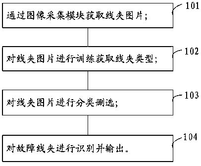
[0047] like figure 1 As shown in the figure, it is a flow chart of a method for automatic detection and defect identification of power grid clamps proposed by the present invention.

[0048] refer to figure 1 , a method for automatic detection and defect identification of wire clips in a power grid, comprising the following steps:

[0049] Step 101, obtain the wire clip picture through the image acquisition module;

[0050] Step 102, train the wire clip picture to obtain the wire clip type;

[0051] Step 103, classify and delete the clip pictures;

[0052] Step 104, identifying and outputting the fault line clamp.

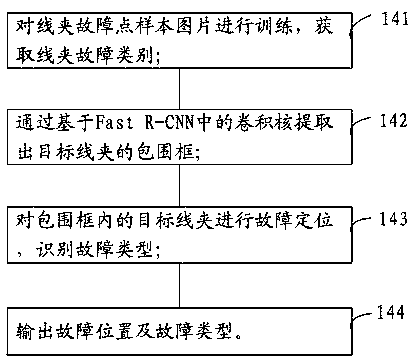
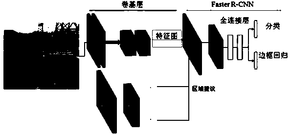
[0053] In the embodiment of the present invention, the image acquisition module is used to collect images of the clamps on the transmission line, and the Faster R-CNN technology is used to train the pictures of the clamps to obtain the type of clamps and realize the classification of the types of clamps. The training and identification of the fault line clips ...

Embodiment 2

[0078] Based on the same inventive concept as the method for automatic detection and defect identification of power grid clamps in the foregoing embodiments, the present invention also provides an automatic detection and defect identification device for power grid clamps.

[0079] see Figure 5 , an automatic detection and defect identification device for grid wire clips, comprising:

[0080] Image collection module 201, used to obtain the wire clip picture;

[0081] Wire clip type training module 202, for training the wire clip picture to obtain the wire clip type;

[0082] The wire clip classification module 203 is used to classify and delete the wire clip pictures;

[0083] The clamp fault detection module 204 is configured to identify and output faulty clamps.


PUM


Abstract

The invention discloses a method for automatic detection and defect identification of power grid clamps, which includes the following steps: obtaining a clamp picture through an image acquisition module; training the clamp picture to obtain a clamp type; classifying and selecting the clamp pictures; identifying and outputting fault clamp. The invention also discloses a device for automatic detection and defect identification of power grid clamps. The invention collects the image of the clamp on the transmission line through the image acquisition module, trains the clamp picture by adopting theFaster R-CNN technology, and adopts the augmented training technology, so as to solve the defects of long time and slow model update cycle caused by the need of retraining for new clamp features, andthe fault detection of the clamp greatly saves the maintenance cost and makes the line inspection system more efficient and intelligent.

Description

technical field [0001] The invention relates to the technical field of safety of overhead power transmission lines, in particular to a method and device for automatic detection and defect identification of power grid clamps. Background technique [0002] In the overhead transmission line, various transmission lines are intertwined, and the transmission lines may be entangled, pulled, and vibrated with each other, which can easily lead to strand breakage and seriously threaten the safe and reliable operation of the overhead transmission line. As an important device in overhead transmission lines, wire clips can wrap a large number of transmission lines, protect the transmission lines and assist vibration reduction, and greatly extend the service life of the transmission lines. However, overhead transmission lines are used for long-distance power transmission, and they must cross different natural environments during the period. After a long period of exposure to wind and s...

Claims


Application Information

Patent Timeline
Patent Type & Authority Applications(China)
IPC IPC(8): G01N21/84G01N21/88G06K9/00G06K9/62
CPCG01N21/84G01N21/8851G01N2021/8887G01N2021/8883G01N2021/8854G06V20/00G06F18/241
Inventor 张令意李程启郑文杰温招洋郑锋华雄
Owner ANHUI NANRUI JIYUAN POWER GRID TECH CO LTD
Learn More