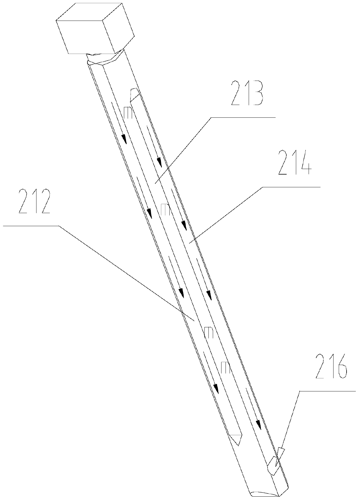
Heavy oil type plunger and barrel assembly

A technology of plunger couples and plungers, which is applied in the field of high-pressure common rail of marine low-speed machines, can solve problems such as irregular gap changes of plunger couples, irregular thermal deformation of plunger couples, frictional failure of plunger surfaces, etc. Achieve the effects of reducing design and processing difficulty, weakening uneven deformation, and balancing temperature distribution

Pending Publication Date: 2019-12-27
CHONGQING HONGJIANG MACHINERY
View PDF0 Cites 0 Cited by
  • Summary
  • Abstract
  • Description
  • Claims
  • Application Information

AI Technical Summary

Problems solved by technology

[0003] (1) In the traditional plunger couple, the plunger chamber of the compressed fuel has more contact with the flowing fuel, and the temperature in the vicinity of it is higher, while the temperature of the part far away from the plunger chamber is lower. Due to the large temperature difference between different positions, Therefore, the thermal deformation of the plunger couple is irregular, so the gap between the plunger couple changes irregularly, which affects the dynamic characteristics and sealing;
[0004] (2) The pressure in the plunger cavity is as high as 1500 bar, and the heavy oil contains high impurities, which may easily lead to frictional failure or excessive wear or even seizure of the plunger surface

Method used


Image

  • Heavy oil type plunger and barrel assembly
  • Heavy oil type plunger and barrel assembly
  • Heavy oil type plunger and barrel assembly

Examples


Embodiment Construction

[0053] Hereinafter, exemplary embodiments of the present invention will be described in more detail with reference to the accompanying drawings. Although exemplary embodiments of the present invention are shown in the drawings, it should be understood that the present invention can be implemented in various forms and should not be limited by the embodiments set forth herein. On the contrary, these embodiments are provided to enable a more thorough understanding of the present invention and to fully convey the scope of the present invention to those skilled in the art.

[0054] Reference Figure 1 to Figure 5 , The present invention provides a heavy oil plunger assembly, including:

[0055] A plunger sleeve assembly, which includes a plunger sleeve 11, an installation through hole for installing the plunger assembly is provided in the plunger sleeve 11, and a fuel collection area 111 connected to the periphery of the plunger sleeve 11 is provided on the plunger sleeve 11 The radia...


PUM


Abstract

The invention relates to a heavy oil type plunger and barrel assembly. The plunger and barrel assembly comprises a plunger sleeve assembly, a plunger assembly, a sealing assembly, wherein the plungersleeve assembly comprises plunger sleeves, and radial oil channels are arranged on the plunger sleeves; the plunger assembly comprises plungers and gap filter elements, and filtering gaps are formed between the gap filter elements and the plungers; the sealing assembly comprises sealing blocks, and oil return collecting cavities are formed between the sealing blocks and the plungers; axial oil channels are arranged on the plunger sleeves; high-pressure heavy oil enters through gaps between the plungers and the gap filter elements, and is subjected to impurity filtering through the filtering gaps, and the high-pressure heavy oil subjected to impurity filtering flows out to the outer surfaces of the plungers; one part of the high-pressure heavy oil flowing out to the outer surfaces of the plungers flows out to a fuel oil collecting area through the radial oil channels; and the other part of the high-pressure heavy oil flows out to the oil return collecting cavities, and the high-pressureheavy oil flowing out to the oil return collecting cavities flows out to the fuel oil collecting area through the axial oil channels. According to the above scheme, the heating state of the plunger and barrel assembly can be improved, so that the overall heating of the plunger sleeves is balanced; and the heavy oil is adopted to lubricate the surfaces of the plungers, the use of lubricating oil is reduced, and the energy is saved.

Description

Technical field [0001] The invention relates to the field of high-pressure common rail for marine low-speed engines, in particular to a heavy oil plunger coupler. Background technique [0002] The fuel system is the heart of the marine engine, and the high-pressure fuel pump is the power source of the fuel system. The plunger assembly is the actuator of the high-pressure fuel pump, and it is also the most precise mechanism in the high-pressure fuel pump. Its life often determines the life of the entire pump. Marine low-speed engines often use heavy oil as the working medium, and its viscosity is as high as 750Cst. The heavy oil needs to be heated to above 150°C during operation, and the heavy oil contains a lot of impurities. During work, the plunger and the assembly are in direct contact with the heavy oil. The high temperature, high viscosity, and high impurity content of the heavy oil will cause the following problems: [0003] (1) In the traditional plunger assembly, the plung...

Claims


Application Information

Patent Timeline
Patent Type & Authority Applications(China)
IPC IPC(8): F02M59/10F02M59/44F02M37/32
CPCF02M37/32F02M59/10F02M59/44F02M59/442F02M59/445
Inventor 侯旭洪涂天华刘惠娥徐辉栗东民张朝磊田梦江
Owner CHONGQING HONGJIANG MACHINERY
Why Eureka
Try Eureka