
Quick connector

A connector and fast technology, applied in the direction of couplings, mechanical equipment, etc., can solve problems such as easy tripping and increasing the number of parts

Inactive Publication Date: 2019-12-24
宁波海连汽配科技有限公司
View PDF2 Cites 0 Cited by
  • Summary
  • Abstract
  • Description
  • Claims
  • Application Information

AI Technical Summary

Problems solved by technology

[0006] The single-side squeeze button of the existing quick connector is too easy to unlock and there is a risk of tripping, while the pull-out buckle of another existing single-side squeeze female connector increases the number of parts

Method used


Image

  • Quick connector
  • Quick connector
  • Quick connector

Examples


Embodiment Construction

[0028] In order to further explain the technical means and effects of the present invention to achieve the intended purpose of the invention, the specific implementation, structure, features and effects of the present invention will be described in detail below in conjunction with the accompanying drawings and preferred embodiments.

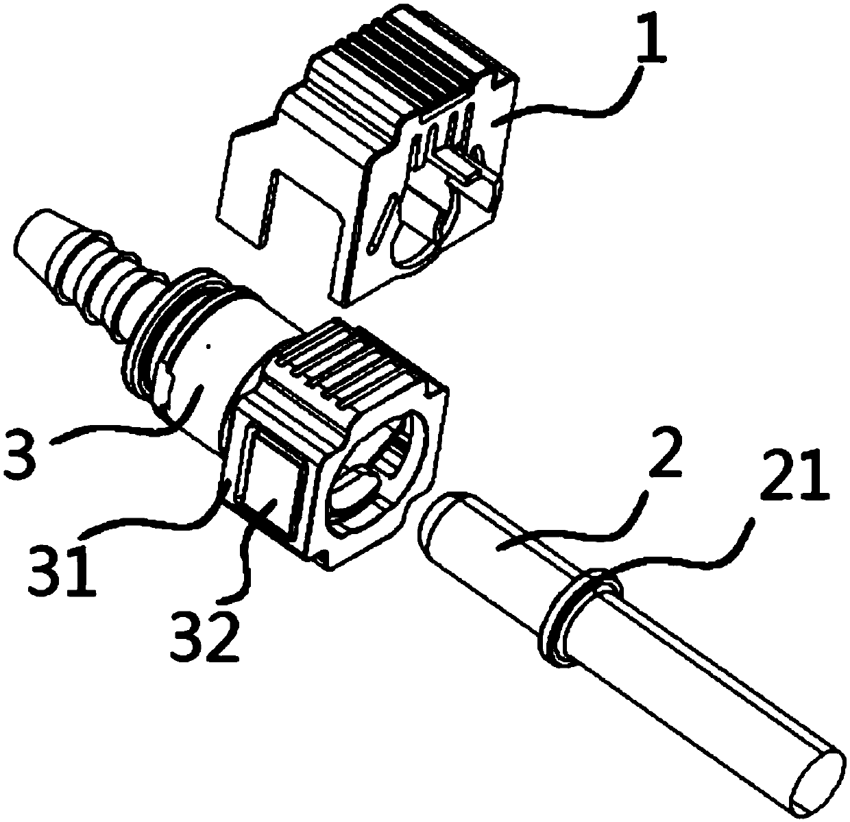
[0029] See Figure 4 , the quick connector of the first embodiment of the present invention includes: a male connector 1 and a female connector 2 with a protruding ring 11;

[0030] See Figure 5 , The female connector 2 includes a housing 21 , a button 22 , an outer retaining ring 23 , an outer O-ring 24 , an inner retaining ring 25 , and an inner O-ring 26 .

[0031] The housing 21 has a button section 3 for accommodating the button 22, a tubular section 4 for accommodating an outer retaining ring 23, an outer O-ring 24, an inner retaining ring 25, and an inner O-ring 26. Pipe handle 5.

[0032] The button segment 3 includes a pair of fixed ...


PUM


Abstract

The invention relates to a quick connector. According to the quick connector, a male connector can drive a button to move from a limit unlocking position corresponding to a locking block and an abutting part to an allowable unlocking position corresponding to the locking block and an avoidance part in the insertion direction, an elastic piece used for keeping the button in the limit unlocking position is arranged between an elastic arm and the end surface of a tubular section, when the button is in the limit unlocking position, the abutting part restricts the locking block from being separatedfrom a convex ring, and when the button is in the allowable unlocking position, an elastic pressing arm can be pressed to drive the elastic arm to open from the center back on to a female connector to enable the locking block to be separated from the convex ring so as to relieve the locking on the female connector.

Description

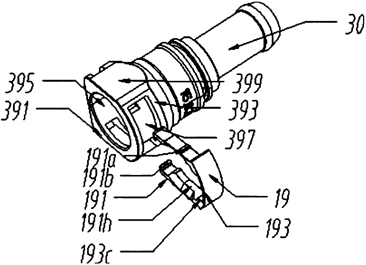
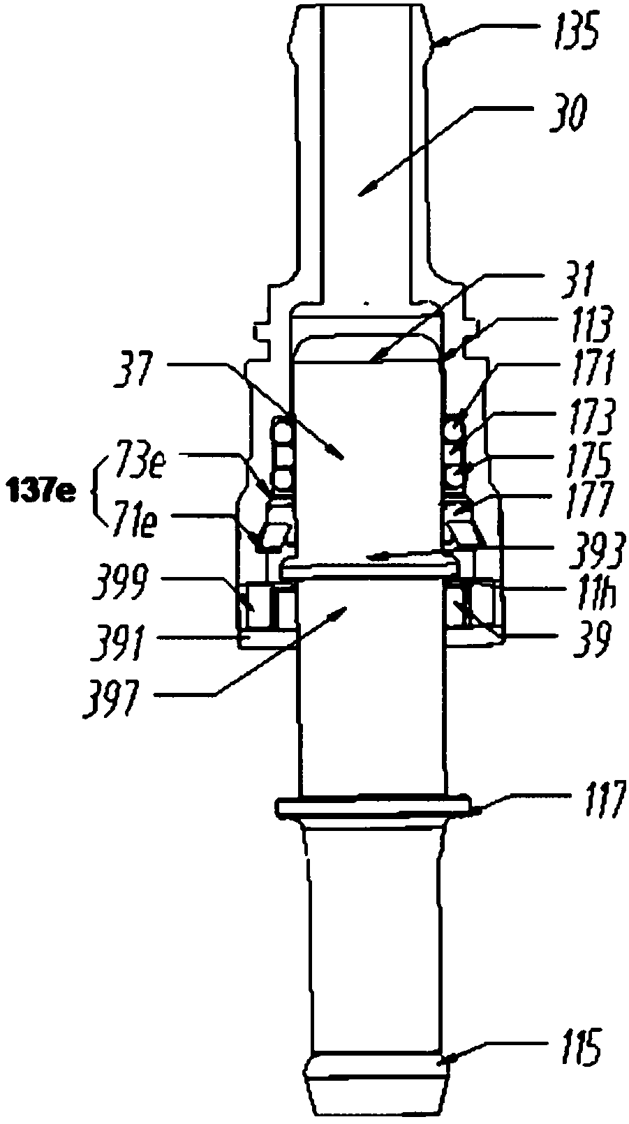
technical field [0001] The invention relates to the field of connectors, in particular to a quick connector. Background technique [0002] See figure 1 , 2 Patent Publication No. CN105633728A discloses a detachable plug-in connector, including an insertion tube (male joint) with a locking fit, for receiving the receiving end (housing) of the insertion tube, for A self-locking device (button) that restricts the movement of the insertion tube, the self-locking device is accommodated in the receiving end, and the self-locking device includes two limiting arms (elastic) with limiting protrusions (locking blocks) arm); fixedly connect the elastic bending part (elastic pressing part) of the two limit arms; the self-locking device also includes two moving parts (sliders), and the receiving end is provided with a The moving part of the limiting arm is fixed on the inner side of the two limiting arms, and the surface of the moving part close to the separating part of the limiting a...

Claims


Application Information

Patent Timeline
Patent Type & Authority Applications(China)
IPC IPC(8): F16L37/088
CPCF16L37/088
Inventor 刘世平
Owner 宁波海连汽配科技有限公司
Learn More