
Eccentric semi-ball valve

A hemispherical valve, eccentric technology, applied in the direction of valve details, valve device, valve housing structure, etc., can solve the problems of eccentric hemispherical valve easy to wear and other problems, achieve the effect of smooth opening and closing, lower resistance, and small switching torque

Pending Publication Date: 2019-12-24
HUHANG TECH GRP CO LTD
View PDF1 Cites 3 Cited by
  • Summary
  • Abstract
  • Description
  • Claims
  • Application Information

AI Technical Summary

Problems solved by technology

[0004] Therefore, the present invention provides an eccentric hemispherical valve, which solves the problem that the existing eccentric hemispherical valve is easy to wear

Method used

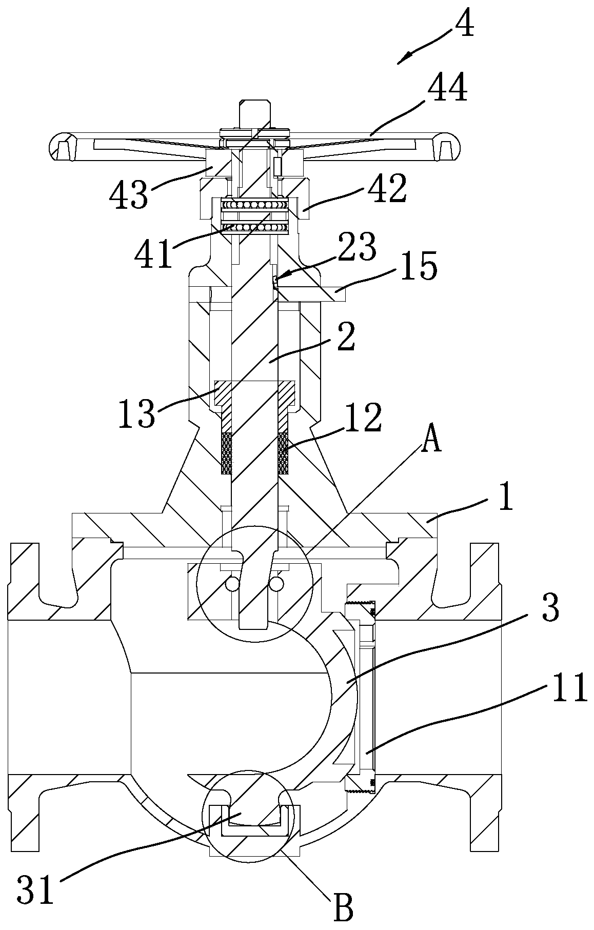

Image

  • Eccentric semi-ball valve
  • Eccentric semi-ball valve
  • Eccentric semi-ball valve

Examples


Embodiment 1

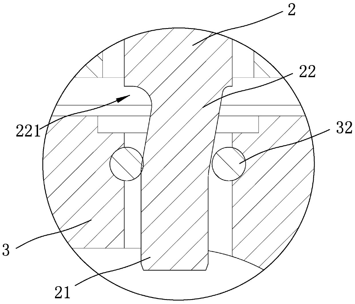
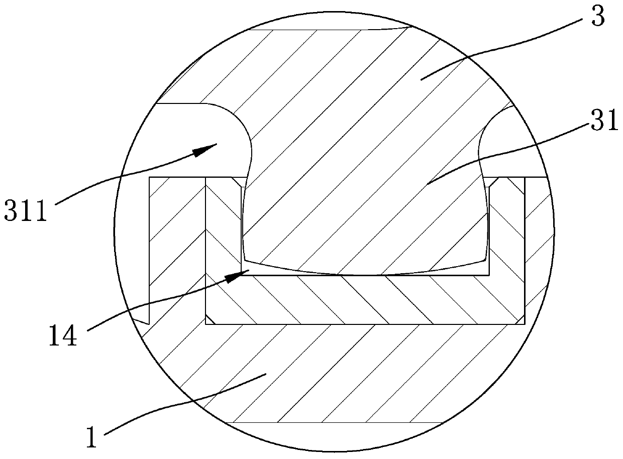
[0022] refer to Figure 1 to Figure 4 , an eccentric hemispherical valve, including a hollow valve body 1 and a rotatable hemispherical spool 3 installed in the valve body 1 through a valve stem 2, the hemispherical spool 3 and the valve installed in the valve body 1 The seat 11 is in a sealed connection, and the upper end of the valve stem 2 is equipped with a transmission mechanism 4 for rotating and lifting the valve stem. Specifically, the transmission mechanism 4 includes a valve that is sequentially installed on the upper end of the valve stem 2 from bottom to top. Bearing 41, bearing gland 42, transmission nut 43 and hand wheel 44 fixed on the transmission nut 43; wherein, a packing 12 and a packing gland 13 for sealing are arranged between the valve stem 2 and the valve body 1;

[0023] The lower end of the valve body 1 is provided with a mounting groove 14 for installing the hemispherical valve core 3, and the lower end of the hemispherical valve core 3 is provided wi...

Embodiment 2

[0031] refer to Figure 5 , Figure 6 , compared with Embodiment 1, the bottom of the pole 31 in this embodiment is provided with a protruding portion 312 arranged radially, and the mounting groove 14 is provided with a reset Spring 141, the return spring 141 is installed towards the direction of the valve seat 11, the installation groove 14 is provided with an arc-shaped insertion groove 142 for accommodating the protrusion 312, when the valve is in a closed state, the The protruding part 312 abuts against the left side of the mounting groove 14 and compresses the return spring 141 , and when the valve is in an open state, the protruding part 312 is embedded in the arc-shaped embedding groove 142 .

[0032] Specifically, the structure of the protrusion and the return spring is provided. When the protrusion contacts the side of the installation groove, the support rod is pushed to compress the return spring, and then the lower end of the hemispherical valve core moves toward ...


PUM


Abstract

The invention relates to the technical field of valves, in particular to an eccentric semi-ball valve comprising a hollow valve body and a semi-ball valve element installed in the valve body through avalve rod and capable of rotating. The semi-ball valve element and a valve base installed in the hollow valve body are connected in a sealed manner A transmission mechanism used for conducting rotation and making the valve rod rise and fall is installed at the upper end of the valve rod. An installation groove used for installing the semi-ball valve element is formed in the lower end of the valvebody. A supporting rod arranged in the installation groove in an embedded manner is arranged at the lower end of the semi-ball valve element. A radial inwards-shrinking groove is formed in the end, close to the semi-ball valve element, on the supporting rod. A straight part with the square section and an inclined part are arranged at the lower end of the valve rod. The inclined part is arranged at the upper end of the straight part and inclines towards the valve base. The straight part is arranged at the upper end of the semi-ball valve element in a penetrating manner. The eccentric semi-ballvalve solves the problem that the sealing face of an existing eccentric semi-ball valve is likely to be abraded.

Description

technical field [0001] The invention relates to the technical field of valves, in particular to an eccentric hemispherical valve. Background technique [0002] In the prior art, such as CN209146374U discloses a full bore eccentric hemispherical valve, comprising a valve body, the right side of the valve body is fixedly connected with studs, the number of the studs is sixteen, the studs The surface of the stud is provided with a valve cover, the surface of the stud is covered with a nut, the left side of the nut is in contact with the valve cover, the top of the valve body is provided with a double stuffing box, and the double stuffing The top of the box extends to the top of the valve body and is fixedly connected with a connecting plate. The top of the connecting plate is provided with an upper valve stem, and the bottom of the upper valve stem penetrates to the bottom of the double stuffing box and extends to the bottom of the valve body. Inner cavity, the bottom of the s...

Claims


Application Information

Patent Timeline
Patent Type & Authority Applications(China)
IPC IPC(8): F16K5/06F16K5/08F16K31/60F16K41/02F16K27/06F16K27/12
CPCF16K5/0663F16K5/08F16K31/60F16K41/02F16K27/067F16K27/12
Inventor 陈思良张书恩谢洪文卢爱山陈超群
Owner HUHANG TECH GRP CO LTD
Learn More