
Cable cutting accurate positioning system

A technology of precise positioning and optical cables, which is applied in metal processing and other directions, can solve problems such as potential safety hazards, swings, and the lack of positioning mechanisms of the device itself, and achieve the effect of improved functional structure and safe picking

Pending Publication Date: 2019-12-24
GUIZHOU NORMAL UNIVERSITY
View PDF1 Cites 0 Cited by
  • Summary
  • Abstract
  • Description
  • Claims
  • Application Information

AI Technical Summary

Problems solved by technology

[0005] The object of the present invention is to provide a precise positioning system for optical cable cutting to solve the problem that when the cable is cut in the above background technology, devices with similar structures lack a reasonable self-positioning mechanism. When the cable is cut, the positioning tool is prone to swing, especially for cutting When the cable is thicker, the device itself with this small structure will swing, and it is difficult to pull out the cable segment synchronously after being cut. When the hand picks up the cut cable segment directly from the cutting area, the distance from the front The side cutting area is relatively close, and there are potential safety hazards

Method used


Image

  • Cable cutting accurate positioning system
  • Cable cutting accurate positioning system
  • Cable cutting accurate positioning system

Examples


Embodiment Construction

[0026] The following will clearly and completely describe the technical solutions in the embodiments of the present invention with reference to the accompanying drawings in the embodiments of the present invention. Obviously, the described embodiments are only some, not all, embodiments of the present invention.

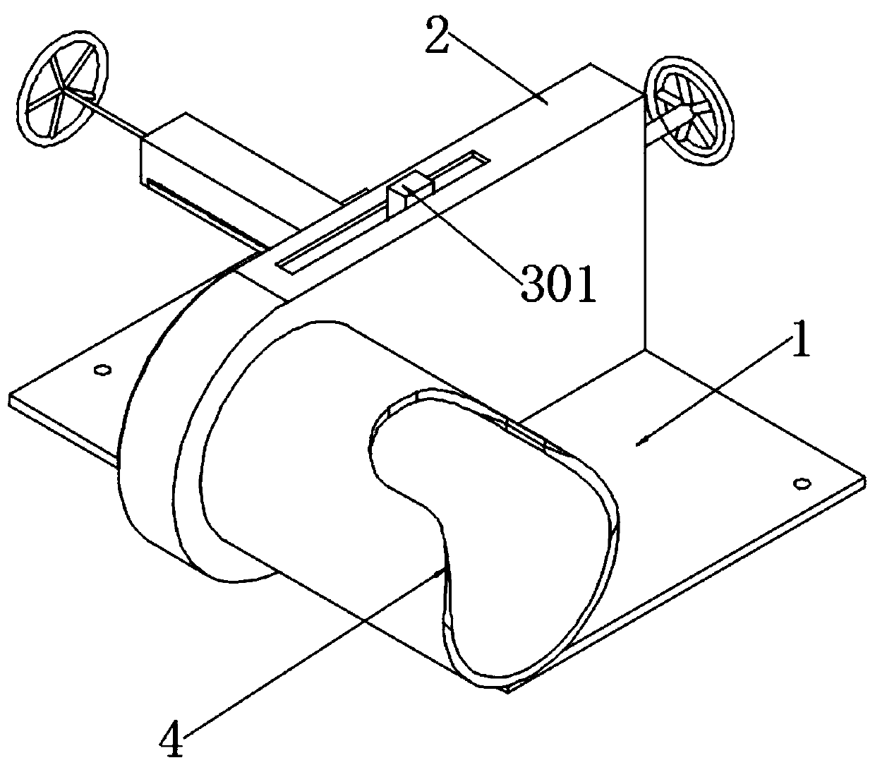
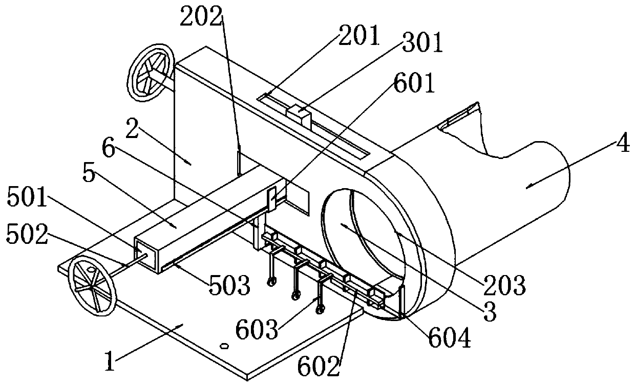
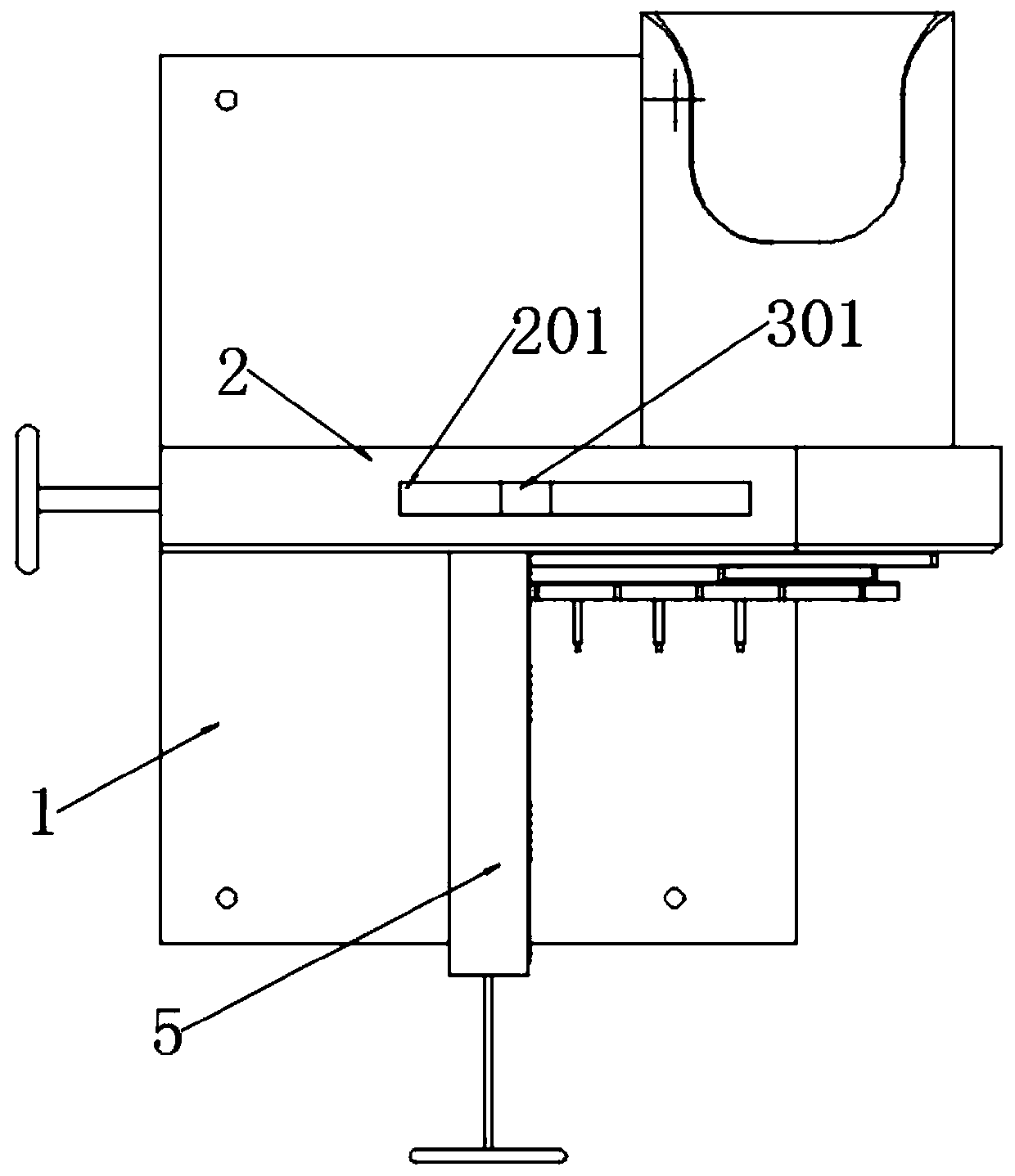
[0027] see Figure 1 to Figure 8 , an embodiment provided by the present invention: a precise positioning system for optical cable cutting, including a bottom fixing plate 1; the bottom fixing plate 1 is a rectangular bottom plate structure, and an installation hole is opened on it, and a vertical cavity is welded in the middle position in a vertical manner 2. The vertical cavity 2 is a hollow cavity structure with a blocking plate 7 welded on the rear side, and a clip body 3 is slidably fitted in the inner cavity, and a wire seat 4 is welded on the front side of the right end of the vertical cavity 2. The wire seat 4 There is a hand notch structure on the top; the l...


PUM


Abstract

The invention discloses a cable cutting accurate positioning system and relates to the technical field of positioning mechanisms. The use safety is improved, the overall design of a clamping structureis good, a cable clamping function is achieved, the function structure is expanded, and a cut cable section is pulled to a rear safety area. The cable cutting accurate positioning system comprises abottom fixing plate which is of a rectangular bottom plate structure, a clamping body is arranged in an inner cavity of the bottom fixing plate in a sliding fit manner, a wire seat is further welded to the front side of the right end face of a vertical cavity, and a hand groove opening structure is formed in the top of the wire seat. The purpose of length setting is achieved with the reference ona ruler assembly, and the cable is pulled outwards towards one side from a clamping notch position synchronously along with loosening of the clamping mechanism. Thus, when the clamping device of the cable cutting accurate positioning system conducts loosening, the broken end section of the cable can be pulled towards one side, the cut cable head can be moved to the rear safety area and get away from a front cutting area and the cut cable is picked more safely.

Description

technical field [0001] The invention relates to the technical field of optical fiber cable processing, in particular to a precise positioning system for optical cable cutting. Background technique [0002] The coaxial optical fiber cable is the signal transmission unit of the microwave communication component. In actual application, it needs to be cut and cut according to the application, such as cutting the end of the applied optical fiber cable head-to-head. [0003] Chinese patent application number CN201320208763.6 discloses a coaxial cable cutting tool, which includes a cable cutting knife seat, a cable fixing block, a cable pressing block, a blade mounting plate, a blade pressing plate and a cutting blade, and the peripheral equipment is a limit sleeve ; The blade mounting plate, the blade pressing plate and the cutting blade are fixed together, and the blade pressing plate is located between the other two, and the three are put into the blade mounting groove of the ca...

Claims


Application Information

Patent Timeline
Patent Type & Authority Applications(China)
IPC IPC(8): B26D7/02
CPCB26D7/02
Inventor 不公告发明人
Owner GUIZHOU NORMAL UNIVERSITY
Learn More