Al technical title is built by PatSnap Al team. It summarizes the technical point description of the patent document.
A switched reluctance and controller technology, which is applied in control systems, AC motor control, electrical equipment casings/cabinets/drawers, etc., can solve the problems of inability to adjust the controller, be easily affected by dust, and inconvenient wiring, etc., to achieve Sufficient and efficient heat dissipation, good dust-proof and dust-guiding effect, and the effect of increasing the suspension installation method
Active Publication Date: 2021-09-21
SUZHOU LEMIFUN ELECTRICAL TECH CO LTD
View PDF9 Cites 0 Cited by
Summary
Abstract
Description
Claims
Application Information
AI Technical Summary
This helps you quickly interpret patents by identifying the three key elements:
Problems solved by technology
Method used
Benefits of technology
Problems solved by technology
[0006] In order to solve the above technical problems, the present invention provides a switched reluctance controller to solve the problem that the existing switched reluctance controller cannot adjust the position of the controller after installation and affect its use. It is also easy to generate heat and easily cause explosion or short circuit and inconvenient wiring to affect the use of the problem
Method used
Image
Click on the blue label to locate the original text in one second.
Reading with bidirectional positioning of images and text.
Examples
Embodiment
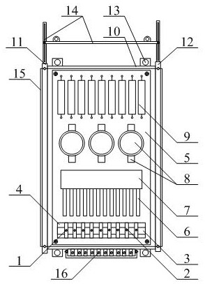
[0055] as attached figure 1 To attach Figure 7 shown
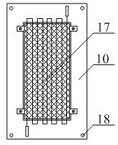
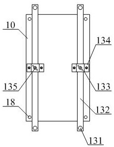
[0056] The present invention provides a switched reluctance controller, comprising a wire fixing screw 1, a wire fixing pressure plate 2, a main wire bar 3, a main wire holder 4, a main circuit board 5 with a power switch, a heat sink 6, a heat conducting block 7, and an electrolytic capacitor 8. Resistor 9, hollow stainless steel connecting plate 10, main lining seat 11, auxiliary lining seat 12, sliding adjustable rail structure 13, suspended position moving plate structure 14, dust-proof deflector structure 15, quick wiring crimping column structure 16. Rapid heat dissipation and heat absorption pipe structure 17 and installation through hole 18. The fixing screws 1 respectively pass through the inner middle position of the fixing pressure plate 2 to thread the main line row 3; the fixing pressure plate 2 is sequentially arranged from left to right It is arranged on the front surface of the main line row 3; the main ...
PUM
Abstract
The present invention provides a switched reluctance controller, including wire fixing screws, wire fixing pressure plates, main wire bars, main wire holders, main circuit boards with power switches, heat sinks, heat conducting blocks, electrolytic capacitors, resistors, and hollow stainless steel connecting plates , the main lining seat, the auxiliary lining seat, the sliding adjustment rail structure, the suspended position moving plate structure, the dust-proof deflector structure, the fast wiring crimping post structure, the rapid heat dissipation heat absorption pipe structure and the installation through hole, the above The wire-fixing screws respectively pass through the inner middle position of the wire-fixing pressure plate to thread the main line row. The present invention fixes the through hole, the linear slide rail, the U-shaped slider, the slider mounting seat and the setting of the wing bolt, which is beneficial to adjust the position of the controller at any time after installation, and is easy to operate; the suspension ear plate, the sliding seat, and the rectangular Through slots, fixed side plates and bolts and nuts are set up, which is beneficial to increase the hanging installation method, and can also adjust the height position to ensure practicality.
Description
technical field [0001] The invention belongs to the technical field of switched reluctance motors, in particular to a switched reluctance controller. Background technique [0002] The switched reluctance system is composed of a switched reluctance controller and a switched reluctance motor. It has the advantages of large starting torque and small starting current. Among them, when the starting current is 15% of the rated current, 100% of the starting current can be obtained. torque, and when the starting torque reaches 150% of the rated torque, the starting current is only 30% of the rated current. Therefore, it can effectively avoid the impact on the power grid and power distribution equipment, and it can frequently rotate forward and reverse, and start and stop frequently. Achieve four-quadrant operation and regenerative braking. Because the switched reluctance system has the advantages of simple structure, high mechanical strength, strong overload capacity, long service ...
Claims
Application Information
Patent Timeline
Application Date:The date an application was filed.
Publication Date:The date a patent or application was officially published.
First Publication Date:The earliest publication date of a patent with the same application number.
Issue Date:Publication date of the patent grant document.
PCT Entry Date:The Entry date of PCT National Phase.
Estimated Expiry Date:The statutory expiry date of a patent right according to the Patent Law, and it is the longest term of protection that the patent right can achieve without the termination of the patent right due to other reasons(Term extension factor has been taken into account ).
Invalid Date:Actual expiry date is based on effective date or publication date of legal transaction data of invalid patent.