
Uninterrupted double-circuit-breaker high-voltage switch cabinet

A high-voltage switchgear and circuit breaker technology, which is applied in the field of high-voltage switchgear, can solve the problems of general ventilation and heat dissipation in the cabinet space, the inability to quickly restore power supply in the switchgear, and the inability to flexibly adjust the load, etc., to achieve good fault isolation performance and protection performance Good, solve the effect of heating and temperature rise

Pending Publication Date: 2019-12-20
QINGYUAN POWER SUPPLY BUREAU OF GUANGDONG POWER GRID CO LTD
View PDF4 Cites 0 Cited by
  • Summary
  • Abstract
  • Description
  • Claims
  • Application Information

AI Technical Summary

Problems solved by technology

[0002] The existing high-voltage switchgear has exposed many problems in actual operation, which restricts the improvement of power supply reliability: First, the ventilation and heat dissipation effect of the cabinet space is average. When the operation reaches 80% of the rated current, the temperature rise generally exceeds the national standard requirement of 70K
The second is that the switchgear needs to be powered off for maintenance and repair; the replacement of current transformers and other components in the cabinet also needs to be powered off; the third is that the load cannot be flexibly adjusted among the busbars of each section; Entire bus failure

Method used


Image

  • Uninterrupted double-circuit-breaker high-voltage switch cabinet
  • Uninterrupted double-circuit-breaker high-voltage switch cabinet
  • Uninterrupted double-circuit-breaker high-voltage switch cabinet

Examples


Embodiment Construction

[0012] The technical solutions in the embodiments of the present invention will be clearly and completely described below in conjunction with the accompanying drawings. Apparently, the described embodiments are only some of the embodiments of the present invention, but not all of them. Based on the embodiments of the present invention, all other embodiments obtained by persons of ordinary skill in the art without making creative efforts belong to the protection scope of the present invention.

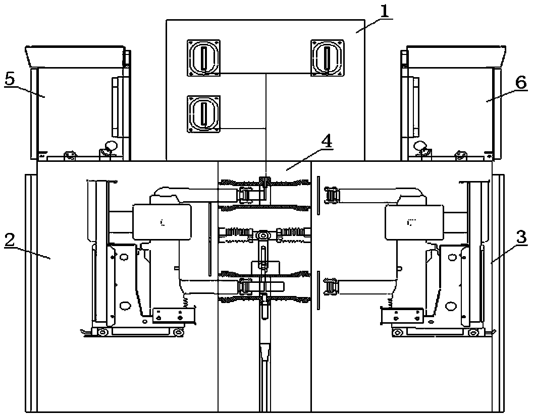
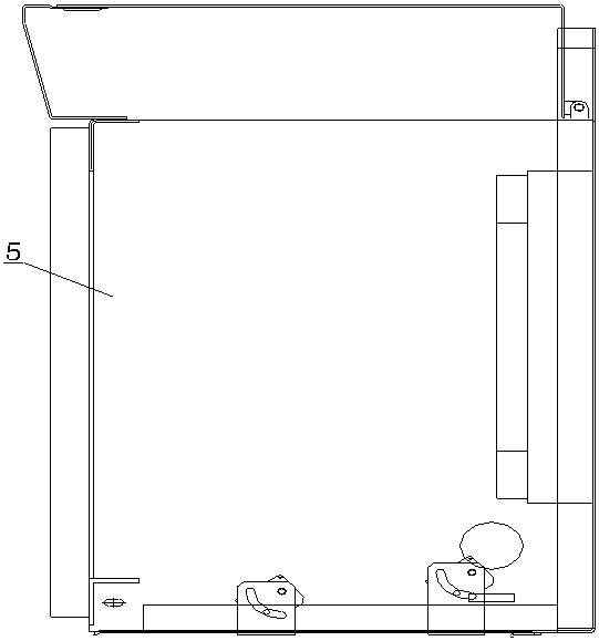
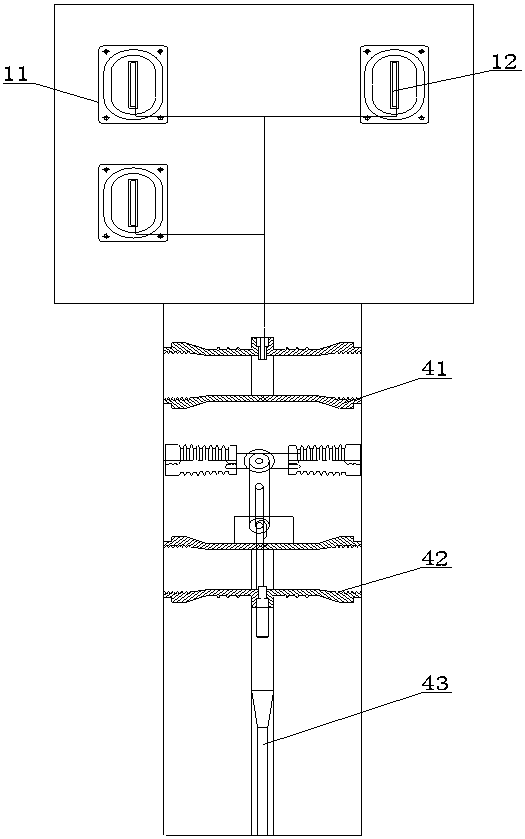
[0013] see Figure 1-6 , a high-voltage switchgear with double circuit breakers without power failure, comprising a main busbar room 1, a main supply circuit breaker room 2, a spare circuit breaker room 3, a cable room 4, a main secondary control room 5 and a spare secondary control room 6, the main One side of the busbar room 1 is electrically connected to the cable room 4, the cable room 4 includes the first wiring 41 and the second wiring 42, the main supply circuit breaker room 2 i...


PUM


Abstract

The invention relates to an uninterrupted double-circuit-breaker high-voltage switch cabinet. The high-voltage switch cabinet comprises a main bus chamber, a main supply circuit breaker chamber, a standby circuit breaker chamber, a cable chamber, a main secondary control chamber and a standby secondary control chamber, wherein one side of the main bus chamber is electrically connected with the cable chamber, a right side of the cable chamber is provided with the standby circuit breaker chamber, the standby circuit breaker chamber is electrically connected with the main secondary control chamber, a left side of the cable chamber is provided with the main supply circuit breaker chamber, the main supply circuit breaker chamber is electrically connected with the standby secondary control chamber, a left side of the main bus chamber is provided with ventilation equipment, and a right side of the main bus chamber is provided with an air outlet. The high-voltage switch cabinet is advantaged in that the high-voltage switch cabinet is formed by splicing and combining functional compartments, has characteristics of standardization and modularization, good protection performance, good fault isolation performance and enough heat dissipation space, can realize switching between a main supply circuit breaker and a standby circuit breaker under the condition of no power failure through powersupply from the standby circuit breaker and a mutual inductor to an outgoing cable, and is convenient to overhaul.

Description

technical field [0001] The invention relates to a high-voltage switchgear, in particular to a high-voltage switchgear with double circuit breakers without power failure. Background technique [0002] The existing high-voltage switchgear has exposed many problems in actual operation, which restricts the improvement of power supply reliability: First, the ventilation and heat dissipation effect of the cabinet space is average. When the operation reaches 80% of the rated current, the temperature rise generally exceeds the national standard requirement of 70K . The second is that the switchgear needs to be powered off for maintenance and repair; the replacement of current transformers and other components in the cabinet also needs to be powered off; the third is that the load cannot be flexibly adjusted among the busbars of each section; The entire busbar is cut off. Contents of the invention [0003] The purpose of the present invention is to provide a high-voltage switchge...

Claims


Application Information

Patent Timeline
Patent Type & Authority Applications(China)
IPC IPC(8): H02B1/30H02B1/56H02J9/06
CPCH02B1/30H02B1/565H02J9/06Y04S20/20Y02B70/30
Inventor 钟万华梁伟成罗泳梁小燕巫立锋
Owner QINGYUAN POWER SUPPLY BUREAU OF GUANGDONG POWER GRID CO LTD
Learn More