
Phase change radiator

A heat sink and phase change technology, applied in indirect heat exchangers, lighting and heating equipment, cooling/ventilation/heating transformation, etc., can solve the problems of restricting the application of gravity heat pipes and unable to meet the installation requirements of power electronic device radiators, etc. To achieve the effect of shortening the phase change period, occupying a small space, and exchanging large amounts of heat

Pending Publication Date: 2019-12-20
株洲时代金属制造有限公司
View PDF0 Cites 4 Cited by
  • Summary
  • Abstract
  • Description
  • Claims
  • Application Information

AI Technical Summary

Problems solved by technology

However, due to the special requirements for the structure of the gravity heat pipe, when in use, the evaporation end of the gravity heat pipe must be placed at the lower part of the radiator, and the condensation end must be located at the upper part of the radiator. This arrangement greatly limits the application of the gravity heat pipe, especially It is unable to meet the installation requirements of power electronic devices for radiators

Method used


Image

  • Phase change radiator
  • Phase change radiator
  • Phase change radiator

Examples


Embodiment Construction

[0022] In order to enable those skilled in the art to better understand the technical solutions in the present application, the technical solutions in the embodiments of the present application will be clearly and completely described below in conjunction with the drawings in the embodiments of the present application. Obviously, the described The embodiments are only some of the embodiments of the present application, but not all of them. Based on the embodiments in this application, all other embodiments obtained by persons of ordinary skill in the art without creative efforts shall fall within the scope of protection of this application.

[0023] The embodiments of the present invention are written in a progressive manner.

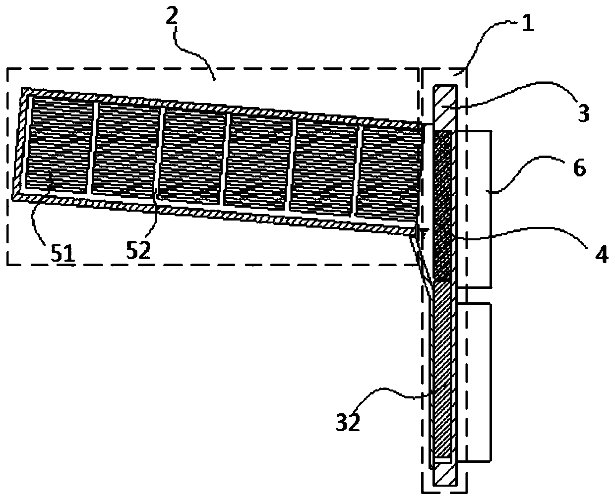
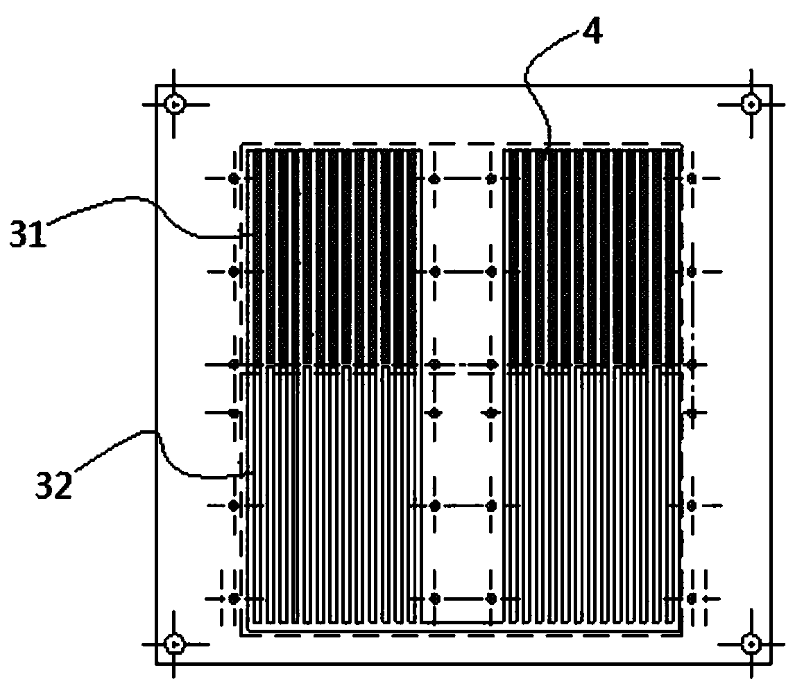
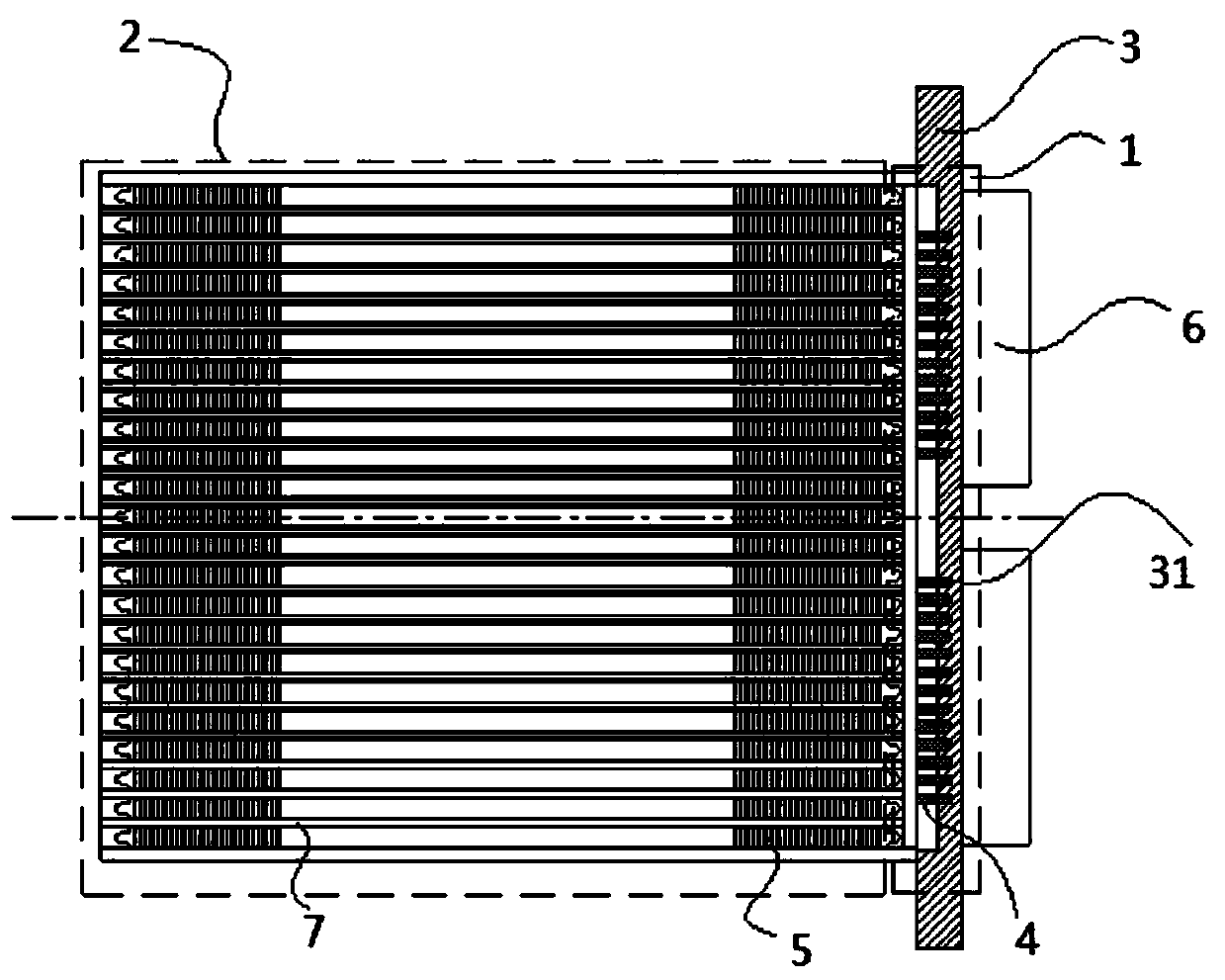
[0024] Such as Figure 1 to Figure 3 As shown, a phase change radiator provided by the present invention includes an evaporating part 1 and a condensing part 2 obliquely arranged on one side of the evaporating part 1. The evaporating part 1 and the con...


PUM


Abstract

The invention provides a phase change radiator. The phase change radiator comprises an evaporation part and a condensation part obliquely arranged on one side of the evaporation part, wherein the evaporation part and the condensation part communicate with each other and form a sealed chamber together, and a refrigerant is injected in the sealed chamber; the evaporation part comprises a vertical substrate and liquid absorption cores arranged on the substrate, first grooves are longitudinally formed in the upper part of the substrate, the liquid absorption cores are embedded in the first grooves, and the lower parts of the liquid absorption cores are immersed in the refrigerant; radiating fins are arranged in the condensation part, and the end, close to the evaporation part, of the condensation part is lower than the end, away from the evaporation part, of the condensation part. The radiator has the advantages of small occupied space, good homeothermy, short refrigerant phase change period and excellent radiation effect, and installation requirements of power electronic devices on the radiator can be met.

Description

technical field [0001] The invention relates to the technical field of heat dissipation, in particular to a phase change radiator. Background technique [0002] Power electronic devices, also known as power semiconductor devices, are mainly used in power conversion and control circuits of power equipment. The power loss of high-power power electronic devices will cause the power electronic devices to heat up and heat up, and if the device temperature is too high, it will shorten the life of the device or even burn the device. Therefore, the cooling problem of the power electronic device must be considered to ensure that the power electronic device is at the rated temperature. work within the range. At present, the commonly used method is to cool the power electronic devices through the radiator. The radiator has the function of conducting and releasing heat without hindering the normal use of the power electronic devices. [0003] Among the many types of radiators, phase c...

Claims


Application Information

Patent Timeline
IPC IPC(8): F28D15/04H05K7/20
CPCF28D15/04H05K7/20336
Inventor 陈传国黄亮刘中涛
Owner 株洲时代金属制造有限公司
Learn More