Conveying belt equipment carrying out automatic oil coating by virtue of gear engagement and used for industrialized production

A technology of conveyor belts and gears, which is applied in the field of conveyor belt equipment for industrialized production, can solve problems that affect work efficiency, require a certain amount of time, stop automatic assembly lines, etc., and achieve the effect of accurately controlling the timing of spraying

Active Publication Date: 2019-12-20
绍兴永乐纺织机械有限公司
View PDF14 Cites 0 Cited by
  • Summary
  • Abstract
  • Description
  • Claims
  • Application Information

AI Technical Summary

Problems solved by technology

[0004] Due to the continuous long-term operation of the conveyor belt, there will be serious friction at the rotating parts, and regular inspection and application of lubricating oil is required. In the prior art, the application of lubricating oil needs to be done manually after the equipment stops working or when it is idling and not carrying goods. Smearing, and it takes a certain amount of time to complete a smearing work, which will cause the automatic assembly line to temporarily stop and affect its work efficiency; in addition, the timing of lubricating oil application is often known based on the abnormal noise from the transmission of the equipment. But at this time, the equipment has been worn for a long time, so a conveyor belt equipment for industrial production that uses gear meshing and automatic oiling came into being.

Method used


Image

  • Conveying belt equipment carrying out automatic oil coating by virtue of gear engagement and used for industrialized production
  • Conveying belt equipment carrying out automatic oil coating by virtue of gear engagement and used for industrialized production
  • Conveying belt equipment carrying out automatic oil coating by virtue of gear engagement and used for industrialized production

Examples


Embodiment Construction

[0024] The technical solutions in the embodiments of the present invention will be clearly and completely described below in conjunction with the accompanying drawings in the embodiments of the present invention. Obviously, the described embodiments are only a part of the embodiments of the present invention, rather than all the embodiments. Based on the embodiments of the present invention, all other embodiments obtained by those of ordinary skill in the art without creative work shall fall within the protection scope of the present invention.

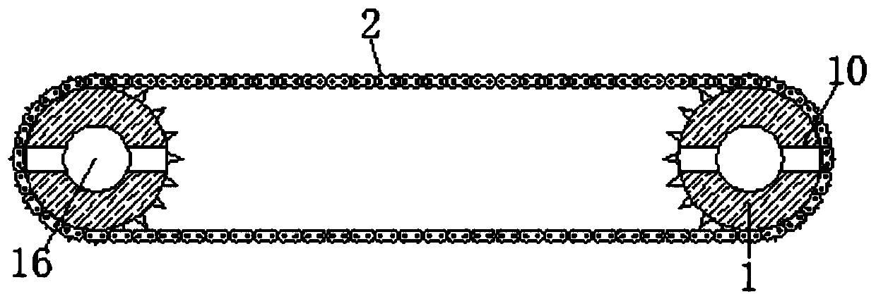
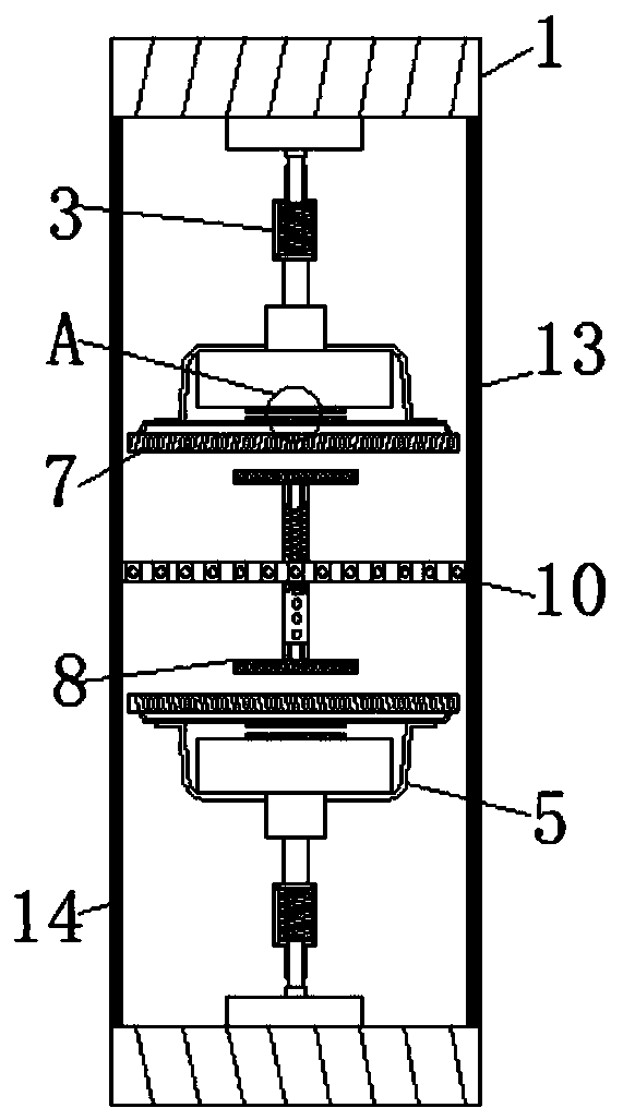
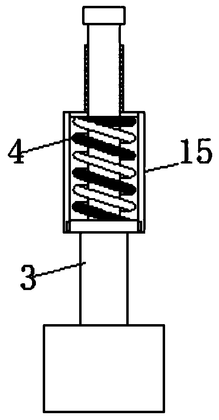
[0025] See Figure 1-5 , A conveyor belt equipment for industrial production using gear meshing and automatic oiling, including a pulley 1, the inner of the pulley 1 is meshed with a rotating shaft 16, the surface of the pulley 1 is glued with a toothed chain 2, and the inner of the pulley 1 is fixedly connected There is an elastic rod 3. If there is a lack of lubricating oil between the toothed chain 2 and the pulley 1, they will rub ag...


PUM


Abstract

The invention relates to the technical field of industrialized oil spraying lubrication for conveying belts, and discloses conveying belt equipment carrying out automatic oil coating by virtue of gearengagement and used for industrialized production. The conveying belt equipment carrying out automatic oil coating by virtue of gear engagement and used for industrialized production comprises a beltwheel, wherein a toothed chain is bonded onto the surface of the belt wheel; an elastic rod is fixedly connected into the belt wheel; a limit pipe is fixedly connected into the elastic rod; a supportframe is fixedly connected to one end away from the belt wheel, of the elastic rod; a friction sheet is fixedly connected into the support frame; and a first gear is movably connected to one side away from the support frame, of the friction sheet. High friction heating is achieved, and the highest temperature can reach 60 DEG C; when the temperature slowly rises, heat is transferred into the limit pipe from the elastic rod; and moreover, when the melting point (about 34-38 DEG C) of cocoa butter in the limit pipe is reached, the cocoa butter is melted and the limit pipe loses a limit effect,the elastic rod stretches and pushes a first gear and a second gear in the support frame to be engaged, then the friction sheet is engaged with the first gear, so that the effect of accurately controlling a spraying opportunity is achieved.

Description

Technical field [0001] The invention relates to the technical field of oil spray lubrication for industrial transmission belts, in particular to a conveyor belt equipment for industrial production that uses gear meshing to automatically apply oil. Background technique [0002] With the development of science and technology, more and more industrial production plants adopt automation equipment. The indispensable part of the automation equipment is the transmission belt. The conveyor belt plays a role in the automatic production. [0003] There are many types of conveyor belt equipment with traction parts, mainly: chain conveyors, slat conveyors, trolley conveyors, etc. Among them, chain conveyors are the most widely used due to their relatively simple production steps and durable characteristics. [0004] As the conveyor belt runs continuously for a long time, serious friction will be generated at the rotating parts, and regular inspection and lubricating oil are required. In the prio...

Claims


Application Information

Patent Timeline
Patent Type & Authority Applications(China)
IPC IPC(8): F16N7/26B65G45/02
CPCB65G45/02F16N7/30F16N2210/24
Inventor 覃玉梅
Owner 绍兴永乐纺织机械有限公司
Why Eureka
Try Eureka