
Wind direction changeable cooling fan

A heat dissipation fan and fan technology, applied to non-variable pumps, components of pumping devices for elastic fluids, pump devices, etc., can solve the problem of affecting overall efficiency, small heat dissipation area, and inability to face or be close to heat sources Configuration and other issues, to achieve the effect of large heat dissipation and enlarge the blowing area

Pending Publication Date: 2019-12-20
太仓市华盈电子材料有限公司
View PDF0 Cites 2 Cited by
  • Summary
  • Abstract
  • Description
  • Claims
  • Application Information

AI Technical Summary

Problems solved by technology

[0002] In electronic equipment, such as laptops, projectors, servers, PCs, etc., in order to cool the heat source, a cooling fan is required, but the installation position of the cooling fan cannot be directly facing the heat source or placed close to the heat source due to space constraints.
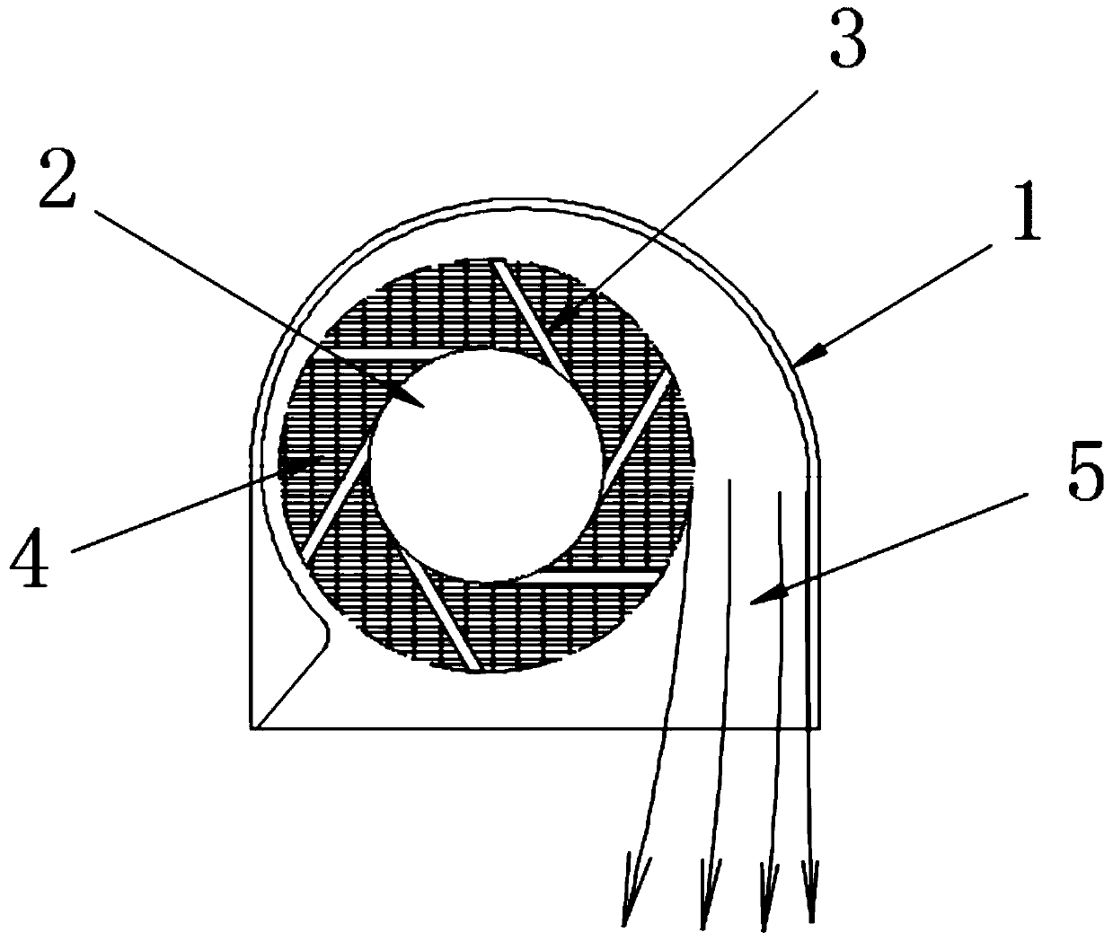
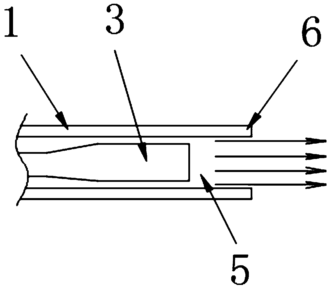
Existing heat dissipation fans inside electronic equipment, such as the heat dissipation fans installed inside notebook computers, projectors, servers, PCs, etc., have certain disadvantages when used: the flow channel design of the existing fans, its main air outlet is concentrated in a single Area, the flow channel design of the air outlet area cannot be changed, and the design has limitations. The design of such a fan flow channel makes the air volume concentrated in the direction of rotation of the air outlet, and the air volume in other areas is weak, resulting in a small heat dissipation area, which affects overall efficiency, as attached figure 1 As shown; the opening area of ​​the air outlet of the cooling fan is a straight face, and the air outlet cannot be blown out in a large area because it is blocked by the direct face. figure 2 shown

Method used


Image

  • Wind direction changeable cooling fan
  • Wind direction changeable cooling fan
  • Wind direction changeable cooling fan

Examples


Embodiment Construction

[0023] In order to further illustrate the various embodiments, the present invention provides accompanying drawings, which are part of the disclosure of the present invention, and are mainly used to illustrate the embodiments, and can be used in conjunction with the relevant descriptions in the specification to explain the operating principles of the embodiments, for reference Those of ordinary skill in the art should be able to understand other possible implementations and advantages of the present invention. The components in the figures are not drawn to scale, and similar component symbols are generally used to represent similar components.

[0024] According to an embodiment of the present invention, a cooling fan capable of changing wind direction is provided.

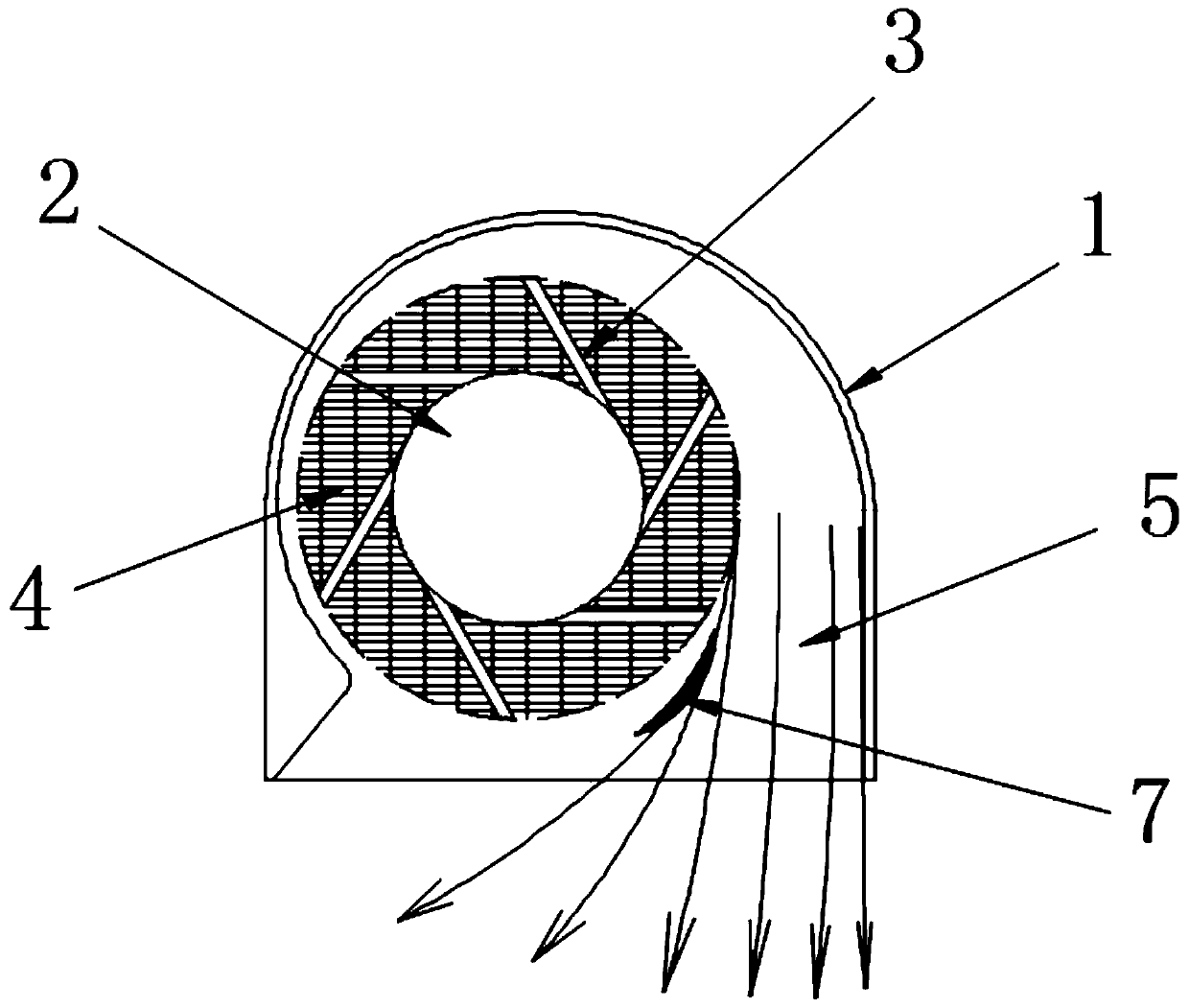
[0025] Now in conjunction with accompanying drawing and specific embodiment the present invention is further described, as Figure 3-5 As shown, a cooling fan capable of changing the wind direction according to an...


PUM


Abstract

The invention discloses a wind direction changeable cooling fan. The wind direction changeable cooling fan comprises a fan frame. A fan driver is arranged in the fan frame. The driving end of the fandriver is provided with a plurality of sets of fan blades. An air inlet net is arranged opposite to the fan driver. The air inlet net is mounted on the fan frame through fasteners. A flow channel is arranged in the position, located on one side of the fan driver, of the fan frame. The position of the flow channel is consistent with the rotating direction of the fan blades. The edge of an air outlet of the fan frame is provided with an air outlet surface. The air outlet surface belongs to an upward arc surface. An arc-shaped plate is arranged in the position, close to the air outlet, of the flow channel. The wind direction changeable cooling fan is provided with the at least one arc-shaped plate which is mounted at the air outlet in the flow channel. The wind direction is changed, so that the cooling fan has the uniform air outlet volume and achieves the directional heat dissipation purpose; the air outlet surface is arranged into the arc surface; through the suction wall effect, the flow guidance design is added to the air outlet position, and the air blowing area of the cooling fan is increased. Accordingly, the higher cooling effect can be achieved.

Description

technical field [0001] The invention relates to the technical field of fan fluid, in particular to a cooling fan capable of changing the wind direction. Background technique [0002] In electronic equipment, such as laptops, projectors, servers, PCs, etc., in order to cool the heat source, cooling fans are required. However, due to space constraints, the installation position of the cooling fan cannot be directly facing the heat source or placed close to the heat source. Existing heat dissipation fans inside electronic equipment, such as the heat dissipation fans installed inside notebook computers, projectors, servers, PCs, etc., have certain disadvantages when used: the flow channel design of the existing fans, its main air outlet is concentrated in a single Area, the flow channel design of the air outlet area cannot be changed, and the design has limitations. The design of such a fan flow channel makes the air volume concentrated in the direction of rotation of the air ou...

Claims


Application Information

Patent Timeline
IPC IPC(8): F04D29/44F04D29/42F04D25/08
CPCF04D29/441F04D29/4226F04D25/08
Inventor 赖进龙
Owner 太仓市华盈电子材料有限公司
Learn More